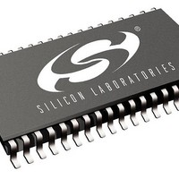
SI3210-BTR Silicon Laboratories Inc, SI3210-BTR Datasheet - Page 15

SI3210-BTR
Manufacturer Part Number
SI3210-BTR
Description
Telecom Line Management ICs Sgl Ch SLIC/Codec w/ DTMF Decoder
Manufacturer
Silicon Laboratories Inc
Datasheet
1.SI3210MPPQX-EVB.pdf
(146 pages)
Specifications of SI3210-BTR
Product
SLIC
Supply Voltage (min)
3.13 V
Supply Current
88 mA
Maximum Operating Temperature
+ 85 C
Minimum Operating Temperature
- 40 C
Mounting Style
SMD/SMT
Number Of Channels
1
Package / Case
TSSOP-38
Lead Free Status / RoHS Status
Lead free / RoHS Compliant
- Current page: 15 of 146
- Download datasheet (860Kb)
Notes:
1. Values and configurations for these components can
2. Only one component per system needed.
3. All circuit ground should have a single-point
4. Si3201 bottom-side exposed pad should be
5. Pin numbers for TSSOP shown.
be derived from Table 19 or from “AN45: Design
Guide for the SI3210 DC-DC Converter”.
connection to the ground plane.
electrically and thermally connected to bulk ground
plane.
RING
TIP
FSYNC
Protection
Figure 9. Si3210/Si3210M Application Circuit Using Si3201
Circuit
PCLK
DRX
DTX
Figure 8. PCM Highway Interface Timing Diagram
t
s u 1
22nF
22nF
C5
C6
C26
t
0.1 F
d 1
1
3
R21
15
TIP
RING
t
h 1
VCC
R29
1
Note 1
0.1 F
C24
2N2222
Q9
R28
GND
SRINGE
Rev. 1.5
t
IRINGN
IRINGP
1
s u 2
STIPE
ITIPN
ITIPP
t
c
t
d 2
VCC
15
13
16
14
11
10
4.02k
4.7 F
t
C18
R7
h 2
220 nF
220 nF
C3
C4
4.02k
R6
200k
196k
196k
200k
200k
470
470
R1
R8
R2
R4
R5
R9
R3
4.7 F
t
C19
r
16
15
20
29
25
28
26
17
19
18
21
STIPE
STIPDC
STIPAC
ITIPN
IRINGN
ITIPP
IRINGP
SRINGE
SVBAT
SRINGAC
SRINGDC
VBAT
C31
DC-DC Converter
10 µF
Circuit
C15
0.1 µF
Si3210/Si3211
t
f
VDC
C16
0.1 µF
FSYNC
RESET
t
CAPM
47 µH
QGND
d 3
SCLK
PCLK
IGMN
CAPP
IGMP
L2
SDO
DRX
IREF
DTX
SDI
INT
CS
C17
0.1 µF
VDC
VCC
38
37
36
1
6
3
4
5
2
7
24
22
11
12
14
13
C30
243
R15
10 µF
10 F
C2
10 F
C1
Note 2
VCC
SPI Bus
R32
10 k
R26
10k
PCM
Bus
2
40.2k
R14
2
15
Related parts for SI3210-BTR
Image
Part Number
Description
Manufacturer
Datasheet
Request
R
Part Number:
Description:
C°/SI3210 QFN EVALUATION BOARD WITH DISCRETE LINE INTERFACE
Manufacturer:
Silicon Laboratories Inc
Datasheet:
Part Number:
Description:
QFN 38/I°/SINGLE-CHANNEL SLIC/CODEC WITH DTMF DECODER AND BJT/INDUCTOR DC-D
Manufacturer:
Silicon Laboratories Inc
Part Number:
Description:
IC SLIC/CODEC PROGRAMMBL 38TSSOP
Manufacturer:
Silicon Laboratories Inc
Datasheet:
Part Number:
Description:
IC SLIC/CODEC PROG 38TSSOP
Manufacturer:
Silicon Laboratories Inc
Datasheet:

Part Number:
Description:
IC SLIC/CODEC PROG 38QFN
Manufacturer:
Silicon Laboratories Inc
Datasheet:
Part Number:
Description:
IC PROSLIC W/DC-DC CONV 38TSSOP
Manufacturer:
Silicon Laboratories Inc
Datasheet:
Part Number:
Description:
IC SLIC/CODEC PROG 38TSSOP
Manufacturer:
Silicon Laboratories Inc
Datasheet:

Part Number:
Description:
Telecom Line Management ICs Sgl Ch SLIC/Codec w/ DTMF Decoder
Manufacturer:
Silicon Laboratories Inc
Datasheet:
Part Number:
Description:
SLIC 1-CH 60dB 41mA 3.3V/5V 38-Pin QFN EP
Manufacturer:
Silicon Laboratories Inc
Datasheet:
Part Number:
Description:
Manufacturer:
Silicon Laboratories Inc
Datasheet:
Part Number:
Description:
Manufacturer:
Silicon Laboratories Inc
Datasheet:
Part Number:
Description:
SLIC 1-CH 60dB 41mA 3.3V/5V 38-Pin TSSOP T/R
Manufacturer:
Silicon Laboratories Inc
Datasheet:

Part Number:
Description:
SWITCH,DC-MAIN,ESTOP,32A
Manufacturer:
IMO PRECISION CONTROLS
Datasheet:

Part Number:
Description:
SWITCH,DISCONNECT,32A,DC
Manufacturer:
IMO PRECISION CONTROLS
Datasheet:
Part Number:
Description:
SMD/C°/SINGLE-ENDED OUTPUT SILICON OSCILLATOR
Manufacturer:
Silicon Laboratories Inc


