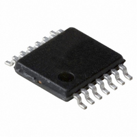
PCA2125TS/1,112 NXP Semiconductors, PCA2125TS/1,112 Datasheet - Page 20

PCA2125TS/1,112
Manufacturer Part Number
PCA2125TS/1,112
Description
IC CMOS RTC/CALENDAR 14-TSSOP
Manufacturer
NXP Semiconductors
Type
Clock/Calendar/Alarmr
Datasheet
1.PCA2125TS1112.pdf
(36 pages)
Specifications of PCA2125TS/1,112
Package / Case
14-TSSOP
Time Format
HH:MM:SS (12/24 hr)
Date Format
YY-MM-DD-dd
Interface
SPI, 3-Wire Serial
Voltage - Supply
1.3 V ~ 5.5 V
Operating Temperature
-40°C ~ 125°C
Mounting Type
Surface Mount
Function
Clock, Calendar
Supply Voltage (max)
5.5 V
Supply Voltage (min)
1.3 V
Maximum Operating Temperature
+ 125 C
Minimum Operating Temperature
- 40 C
Mounting Style
SMD/SMT
Rtc Bus Interface
Serial
Lead Free Status / RoHS Status
Lead free / RoHS Compliant
For Use With
OM6292 - DEMO BOARD PCA2125 RTC
Memory Size
-
Lead Free Status / RoHS Status
Lead free / RoHS Compliant, Lead free / RoHS Compliant
Other names
935283386112
PCA2125TS/1
PCA2125TS/1
PCA2125TS/1
PCA2125TS/1
NXP Semiconductors
PCA2125_1
Product data sheet
8.7.3 Alarm interrupts
The timing shown for clearing bit TF in
mode i.e. when bit TI_TP = 0, where the pulse can be shortened by setting bit TIE = 0.
Generation of interrupts from the alarm function is controlled via bit AIE. If bit AIE is
enabled, the INT pin follows the status of bit AF. Clearing bit AF will immediately clear INT.
No pulse generation is possible for alarm interrupts; see
Fig 13. Example of shortening the INT pulse by clearing the TF flag
Fig 14. AF timing
(1) Indicates normal duration of INT pulse (bit TI_TP = 1).
Example where only the minute alarm is used and no other interrupts are enabled.
countdown counter
minute counter
minute alarm
instruction
instruction
SCL
INT
AF
SCL
Rev. 01 — 28 July 2008
INT
TF
44
45
01
45
n
Figure 13
CLEAR INSTRUCTION
CLEAR INSTRUCTION
is also valid for the non-pulsed interrupt
Figure
SPI Real-time clock/calendar
8th clock
8th clock
14.
001aaf910
PCA2125
001aaf909
© NXP B.V. 2008. All rights reserved.
(1)
20 of 36


