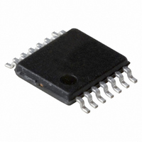
PCA2125TS/1,112 NXP Semiconductors, PCA2125TS/1,112 Datasheet - Page 4

PCA2125TS/1,112
Manufacturer Part Number
PCA2125TS/1,112
Description
IC CMOS RTC/CALENDAR 14-TSSOP
Manufacturer
NXP Semiconductors
Type
Clock/Calendar/Alarmr
Datasheet
1.PCA2125TS1112.pdf
(36 pages)
Specifications of PCA2125TS/1,112
Package / Case
14-TSSOP
Time Format
HH:MM:SS (12/24 hr)
Date Format
YY-MM-DD-dd
Interface
SPI, 3-Wire Serial
Voltage - Supply
1.3 V ~ 5.5 V
Operating Temperature
-40°C ~ 125°C
Mounting Type
Surface Mount
Function
Clock, Calendar
Supply Voltage (max)
5.5 V
Supply Voltage (min)
1.3 V
Maximum Operating Temperature
+ 125 C
Minimum Operating Temperature
- 40 C
Mounting Style
SMD/SMT
Rtc Bus Interface
Serial
Lead Free Status / RoHS Status
Lead free / RoHS Compliant
For Use With
OM6292 - DEMO BOARD PCA2125 RTC
Memory Size
-
Lead Free Status / RoHS Status
Lead free / RoHS Compliant, Lead free / RoHS Compliant
Other names
935283386112
PCA2125TS/1
PCA2125TS/1
PCA2125TS/1
PCA2125TS/1
NXP Semiconductors
Table 4.
Bits labeled ‘-’ are not implemented and will return a logic 0 when read. Bit positions labeled ‘0’ should always be written with
logic 0.
[1]
PCA2125_1
Product data sheet
Address Register name
00h
01h
02h
03h
04h
05h
06h
07h
08h
09h
0Ah
0Bh
0Ch
0Dh
0Eh
0Fh
Ten’s place.
Control_1
Control_2
Seconds
Minutes
Hours
Days
Weekdays
Months
Years
Minute_alarm
Hour_alarm
Day_alarm
Weekday_alarm
CLKOUT_control
Timer_control
Countdown_timer
Register overview
8.1 Register overview
The time registers are encoded in BCD to simplify application use. Other registers are
either bit-wise or standard binary.
•
•
•
•
•
The first two registers at addresses 00h and 01h (Control_1 and Control_2) are used
as control registers.
Registers at addresses 02h to 08h (Seconds, Minutes, Hours, Days, Weekdays,
Months, Years) are used as counters for the clock function. Seconds, minutes, hours,
days, months and years are all coded in Binary Coded Decimal (BCD) format. When
one of the RTC registers is read the contents of all counters are frozen. Therefore,
faulty reading of the clock/calendar during a carry condition is prevented.
Registers at addresses 09h to 0Ch (Minute_alarm, Hour_alarm, Day_alarm,
Weekday_alarm) define the alarm condition.
Register at address 0Dh (CLKOUT_control) defines the clock out mode.
Registers at addresses 0Eh and 0Fh (Timer_control and Countdown_timer) are used
for the countdown timer function. The countdown timer has four selectable source
clocks allowing for countdown periods in the range from less than 1 ms to more than 4
hours. There are also two pre-defined timers which can be used to generate an
interrupt once per second or once per minute. These are defined in register Control_2
(01h).
EXT_TEST
AEN_M
AEN_W
AEN_H
AEN_D
RF
TE
MI
7
-
-
-
-
-
-
-
SI
6
0
-
-
-
-
-
-
-
-
-
-
-
YEARS
Rev. 01 — 28 July 2008
MINUTE_ALARM
AMPM
AMPM
STOP
MSF
5
-
-
-
-
-
SECONDS
MINUTES
HOUR_ALARM
[1]
DAY_ALARM
HOURS
HOUR_ALARM
DAYS
COUNTDOWN_TIMER
MONTHS
HOURS
[1]
[1]
TI_TP
[1]
[2]
[1]
4
0
-
-
-
-
[1]
[2]
[1]
Bit
[1]
[1]
POR_OVRD
AF
3
-
-
-
-
SPI Real-time clock/calendar
MINUTE_ALARM
HOUR_ALARM
HOUR_ALARM
DAY_ALARM
SECONDS
MINUTES
MONTHS
12_24
HOURS
HOURS
YEARS
DAYS
TF
WEEKDAY_ALARM
2
-
PCA2125
© NXP B.V. 2008. All rights reserved.
WEEKDAYS
COF
AIE
1
0
CTD
TIE
4 of 36
0
0


