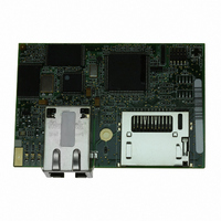
20-101-1196 Rabbit Semiconductor, 20-101-1196 Datasheet - Page 100

20-101-1196
Manufacturer Part Number
20-101-1196
Description
MODULE RABBITCORE RCM3900
Manufacturer
Rabbit Semiconductor
Datasheet
1.20-101-1196.pdf
(168 pages)
Specifications of 20-101-1196
Module/board Type
MPU Core Module
For Use With/related Products
RCM3900
Lead Free Status / RoHS Status
Lead free / RoHS Compliant
Other names
20-101-1196
316-1155
316-1155
- Current page: 100 of 168
- Download datasheet (3Mb)
B.4.8 Other Prototyping Board Modules
An optional LCD/keypad module is available that can be mounted on the Prototyping
Board. The signals on headers LCD1JB and LCD1JC will be available only if the LCD/
keypad module is installed. Refer to Appendix C, “LCD/Keypad Module,” for complete
information.
B.4.9 Quadrature Decoder
Four quadrature decoder inputs are available on screw-terminal header J5. To use the PF0
input from the Rabbit microprocessor, which goes to the QD1B input, remember to recon-
figure the jumper on header JP3 to jumper pins 1–2.
Additional information on the use of the quadrature decoders on Parallel Port F is pro-
vided in the Rabbit 3000 Microprocessor User’s Manual.
B.4.10 Stepper-Motor Control
The Prototyping Board can be used to demonstrate the use of the RCM3900 to control a
stepper motor. Stepper motor control typically directs moves in two orthogonal directions,
and so two sets of stepper-motor control circuits are provided for via screw-terminal head-
ers J3 and J4.
In order to use the stepper-motor control, install two Texas Instruments L293DN chips at
locations U2 and U3 (shown in Figure B-10). These chips are readily available from your
favorite electronics parts source, and may be purchased through our
Web store
as part
number 660-0205.
Figure B-10. Install Four-Channel Push-Pull Driver Chips
RabbitCore RCM3900 User’s Manual
100
Related parts for 20-101-1196
Image
Part Number
Description
Manufacturer
Datasheet
Request
R

Part Number:
Description:
COMPUTER SGL-BRD BL2500 29.4MHZ
Manufacturer:
Rabbit Semiconductor
Datasheet:

Part Number:
Description:
COMPUTER SGL-BRD BL2500 29.4MHZ
Manufacturer:
Rabbit Semiconductor
Datasheet:

Part Number:
Description:
DISPLAY GRAPHIC 12KEY PROG OP670
Manufacturer:
Rabbit Semiconductor
Datasheet:

Part Number:
Description:
DISPLAY GRAPHIC 12KEY ETH OP6700
Manufacturer:
Rabbit Semiconductor
Datasheet:

Part Number:
Description:
COMPUTER SINGLE-BOARD BL2030
Manufacturer:
Rabbit Semiconductor

Part Number:
Description:
COMPUTER SGL-BOARD ETH BL2010
Manufacturer:
Rabbit Semiconductor

Part Number:
Description:
MODULE OP6810 W/O ETH/MEM EXPANS
Manufacturer:
Rabbit Semiconductor
Datasheet:

Part Number:
Description:
COMPUTER SINGLE-BOARD BL2020
Manufacturer:
Rabbit Semiconductor

Part Number:
Description:
COMPUTER BL2010 W/FRICTION LOCK
Manufacturer:
Rabbit Semiconductor

Part Number:
Description:
COMPUTER BL2020 W/FRICTION LOCK
Manufacturer:
Rabbit Semiconductor

Part Number:
Description:
COMPUTER SGL-BRD BL2500 44.2MHZ
Manufacturer:
Rabbit Semiconductor
Datasheet:

Part Number:
Description:
COMPUTER SGL-BOARD FULL BL2000
Manufacturer:
Rabbit Semiconductor

Part Number:
Description:
COMPUTER SINGLE-BOARD BL2110
Manufacturer:
Rabbit Semiconductor

Part Number:
Description:
COMPUTER SGL-BRD 29.4MHZ BL2610
Manufacturer:
Rabbit Semiconductor
Datasheet:

Part Number:
Description:
INTERFACE OP6800 512K FLASH&SRAM
Manufacturer:
Rabbit Semiconductor
Datasheet:


