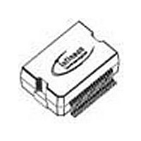
TLE6240GPNT Infineon Technologies, TLE6240GPNT Datasheet - Page 21

TLE6240GPNT
Manufacturer Part Number
TLE6240GPNT
Description
Manufacturer
Infineon Technologies
Datasheet
1.TLE6240GPNT.pdf
(37 pages)
Specifications of TLE6240GPNT
Switch Type
Low Side
Power Switch Family
TLE6240
Input Voltage
-0.3 to 7V
Power Switch On Resistance
1Ohm
Output Current
500mA
Number Of Outputs
16
Mounting
Surface Mount
Supply Current
5mA
Package Type
DSO
Operating Temperature (min)
-40C
Operating Temperature (max)
150C
Operating Temperature Classification
Automotive
Pin Count
36
Lead Free Status / Rohs Status
Compliant
6
6.1
The 16 outputs of the TLE6240GP can be controlled via serial interface. Additionally eight of these 16 channels
can alternatively be controlled in parallel (Channel 1 to 4 and 9 to 12) for PWM applications.
6.1.1
A Boolean operation (either AND or OR) is performed on each of the parallel inputs and respective SPI data bits,
in order to determine the states of the respective outputs. The type of Boolean operation performed is programmed
via the serial interface.
The parallel inputs are high or low active depending on the PRG pin. If the parallel input pins are not connected
(independent of high or low activity) it is guaranteed that the outputs 1 to 4 and 9 to 12 are switched off. The PRG
pin itself is internally pulled up when it is not connected.
PRG - Program pin.
•
•
6.1.2
6.1.3
Each output is independently controlled by an output latch and a common reset line, which disables all outputs.
The Serial Input (SI) is read on the falling edge of the serial clock. A logic high input ‘data bit’ turns the respective
output channel ON, a logic low ‘data bit’ turns it OFF.
CS must be low whilst shifting all the serial data into the device. A low-to-high transition of CS transfers the serial
data input bits to the output control buffer.
The 16 channels of the TLE6240GP are divided up into two parts for the control of the outputs (ON, OFF) and the
diagnosis information.
Serial Input (SI) information consists of 16 bit. 8 bit contain the input driver information for channel 1 to 8 or for
channel 9 to 16. The remaining 8 bits are used to program a certain operation mode.
Serial Output (SO) data consists of 16 bit containing the diagnosis information for channels 1 to 8 or channels 9
to 16 with two bits per channel.
Channel 1 to 8:
•
•
•
Channel 9 to 16:
•
•
•
Data Sheet
PRG = High (
PRG = Low (GND): Parallel inputs Channel 1 to 4 and 9 to 12 are low active
Control Byte 1: Operation mode and diagnosis select for channels 1 to 8
Data Byte1: ON/OFF information for channel 1 to 8
DIAG_1: Diagnosis data for channels 1 to 8
Control Byte 2: Operation mode and diagnosis select for channels 9 to 16
Data Byte2: ON/OFF information for channel 9 to 16
DIAG_2: Diagnosis data for channels 9 to 16
Control of the Device
Output Stage Control
Parallel Control and PRG - Pin
Serial Control of the Outputs: SPI Protocol
Overview
V
S
): Parallel inputs Channel 1 to 4 and 9 to 12 are high active
21
Smart 16-Channel Low-Side Switch
Control of the Device
Rev.3.3, 2010-02-15
TLE6240GP


