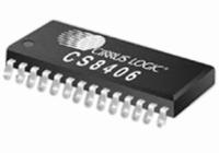
CS8406-DZZ Cirrus Logic Inc, CS8406-DZZ Datasheet - Page 41

CS8406-DZZ
Manufacturer Part Number
CS8406-DZZ
Description
IC XMITTER DGTL 192KHZ 28TSSOP
Manufacturer
Cirrus Logic Inc
Type
Digital Audio Interface Transmitterr
Datasheet
1.CS8406-CZZ.pdf
(42 pages)
Specifications of CS8406-DZZ
Applications
Automotive Audio
Mounting Type
Surface Mount
Package / Case
28-TSSOP
Audio Control Type
Digital
Control Interface
3 Wire, Serial
Control / Process Application
AV & DVD Receivers, CD-R, Digital Mixing Consoles
Supply Voltage Range
3.14V To 5.25V
Lead Free Status / RoHS Status
Lead free / RoHS Compliant
For Use With
598-1017 - BOARD EVAL FOR CS8416 RCVR
Lead Free Status / RoHS Status
Lead free / RoHS Compliant, Lead free / RoHS Compliant
Other names
598-1722
Available stocks
Company
Part Number
Manufacturer
Quantity
Price
Part Number:
CS8406-DZZ
Manufacturer:
CIRRUS
Quantity:
20 000
DS580F5
16.2
16.2.1 Mode 1: Transmit All Zeros
16.2.2 Mode 2: Block Mode
AES3 User (U) Bit Management
The CS8406 U bit manager has two operating modes:
Mode 1. Transmit all zeros.
Mode 2. Block mode.
16.1.3.2 Two-Byte Mode
There are those applications in which the A and B channel status blocks will not be the same, and the user
is interested in accessing both blocks. In these situations, Two-Byte Mode should be used to access the E
buffer.
In this mode, a read will cause the CS8406 to output two bytes from its control port. The first byte out will
represent the A channel status data, and the 2nd byte will represent the B channel status data. Writing is
similar, in that two bytes must now be input to the CS8406's control port. The A channel status data is first;
B channel status data second.
Mode 1 causes only zeros to be transmitted in the output U data, regardless of E buffer contents. This
mode is intended for the user who wants the output U channel to contain no data.
Mode 2 is very similar to the scheme used to control the C bits. Entire blocks of U data are buffered using
2 block-sized RAMs to perform the buffering. The user has access to the first buffer, denoted the E buffer,
through the control port. It is the only mode in which the user can merge his own U data into the transmit-
ted AES3 data stream. The U buffer access only operates in Two-Byte Mode, since there is no concept
of A and B blocks for user data. The arrangement of the data is as followings: Bit15[A7] Bit14[B7]
Bit13[A6] Bit12 [B6]...Bit1 [A0] Bit0[B0]. The arrangement of the data in the each byte is that the MSB is
the first transmitted bit. The bit for the A subframe is followed by the bit for the B subframe.
CS8406
41


