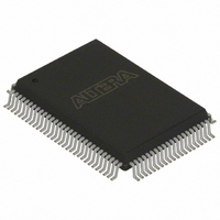
EPC4QI100 Altera, EPC4QI100 Datasheet - Page 50

EPC4QI100
Manufacturer Part Number
EPC4QI100
Description
IC CONFIG DEVICE 4MBIT 100-PQFP
Manufacturer
Altera
Series
EPCr
Datasheet
1.EPC4QI100N.pdf
(116 pages)
Specifications of EPC4QI100
Programmable Type
In System Programmable
Memory Size
4Mb
Voltage - Supply
3 V ~ 3.6 V
Operating Temperature
-40°C ~ 85°C
Package / Case
100-MQFP, 100-PQFP
Lead Free Status / RoHS Status
Contains lead / RoHS non-compliant
Other names
544-2189
Available stocks
Company
Part Number
Manufacturer
Quantity
Price
Company:
Part Number:
EPC4QI100
Manufacturer:
ALTERA
Quantity:
1
Part Number:
EPC4QI100
Manufacturer:
ALTERA/阿尔特拉
Quantity:
20 000
Company:
Part Number:
EPC4QI100N
Manufacturer:
ALTERA
Quantity:
300
Part Number:
EPC4QI100N
Manufacturer:
ALTERA/阿尔特拉
Quantity:
20 000
2–14
Calculating the Size of Configuration Space
Clock Divider
Settings and Guidelines
Configuration Handbook (Complete Two-Volume Set)
When using 1-bit PS configuration mode to serially configure multiple devices, all
configuration data is transmitted through the same DATA line and the devices are
daisy-chained together. Therefore, the total size of the uncompressed configuration
data is equal to the sum of the SRAM-based device’s configuration file size multiplied
by the number of pages used.
When using n-bit PS configuration mode to concurrently configure multiple devices,
each SRAM-based device has its own DATA line from the enhanced configuration
devices. The total size of the uncompressed configuration space is equal to the size of
the largest device’s configuration file size multiplied by n (where n = 1, 2, 4, or 8),
which is then multiplied by the number of pages used. For example, if three devices
are concurrently configured using 4-bit PS configuration mode, the total size of the
uncompressed configuration space is equal to the size of the largest device’s
configuration file multiplied by four.
When using FPP configuration mode, the total size of the uncompressed
configuration space is equal to the sum of the SRAM-based device’s configuration file
size multiplied by the number of pages used.
For configuration file sizes of SRAM-based devices, refer to the
Handbook.
The clock divider value specifies the clock frequency divisor, which is used to
determine the DCLK frequency, or how fast the data is clocked into the SRAM-based
device. You must consider the maximum DCLK input frequency of the targeted SRAM
device family while selecting the clock input and divider settings. For DCLK timing
specifications of SRAM-based devices, refer to the
Enhanced configuration devices can use either the internal oscillator or an external
clock source to clock data into SRAM-based devices, as shown in
enhanced configuration device’s internal oscillator runs at nominal speeds of 10, 33,
50, or 66 MHz. The minimum and maximum speeds are shown in the
Configuration Device Data
accept an external clock source running at speeds of up to 100 MHz.
Sheet. Additionally, the enhanced configuration device can
Chapter 2: Altera Enhanced Configuration Devices
Configuration
© December 2009 Altera Corporation
Configuration
Handbook.
Figure
Enhanced
2–13. The
Clock Divider


