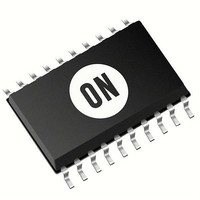
NCP1081DER2G ON Semiconductor, NCP1081DER2G Datasheet - Page 14

NCP1081DER2G
Manufacturer Part Number
NCP1081DER2G
Description
IC CONV CTLR POE-PD 40W 20-TSSOP
Manufacturer
ON Semiconductor
Type
Power over Ethernet Switch (PoE)r
Datasheet
1.NCP1081DER2G.pdf
(17 pages)
Specifications of NCP1081DER2G
Applications
Remote Peripherals (Industrial Controls, Cameras, Data Access)
Internal Switch(s)
Yes
Current Limit
1.1A
Voltage - Supply
0 V ~ 57 V
Operating Temperature
-40°C ~ 85°C
Mounting Type
Surface Mount
Package / Case
20-TSSOP Exposed Pad, 20-eTSSOP, 20-HTSSOP
Output Voltage
9 V
Switching Frequency
250 KHz
Maximum Operating Temperature
+ 85 C
Mounting Style
SMD/SMT
Minimum Operating Temperature
- 40 C
Operating Temperature Range
- 40 C to + 85 C
Output Power
40 W
Input Voltage
57V
Supply Current
510mA
Digital Ic Case Style
TSSOP
No. Of Pins
20
Duty Cycle (%)
80%
Uvlo
38V
Frequency
500kHz
Svhc
No SVHC (20-Jun-2011)
Rohs Compliant
Yes
Lead Free Status / RoHS Status
Lead free / RoHS Compliant
Available stocks
Company
Part Number
Manufacturer
Quantity
Price
Company:
Part Number:
NCP1081DER2G
Manufacturer:
IXYS
Quantity:
7 710
capacitor is charged with the INRUSH current (in order to
limit the internal power dissipation of the pass−switch).
Once the Cpd capacitor is fully charged, the current limit
switches from the inrush current to the current limit level
(ilim1) as shown in Figure 12. This transition occurs when
both following conditions are satisfied:
Vds_pgood is true (meaning that RTN−VPORTN
below the high level of Vds_pgood). This mechanism allows
a current level transition without any current spike in the
pass−switch because the operational current limit (ilim1) is
enabled once the pass−switch is not limiting the current
anymore, meaning that the Cpd capacitor is fully charged.
When VPORT reaches the UVLO_on level, the Cpd
The operational current limit will stay selected as long as
1. The VDS of the pass−switch is below the
2. The pass−switch is no longer in current limit
Vds_pgood low level (1 V typical).
mode, meaning the gate of the pass−switch is
“high” (above 2 V typical).
VPORTNx
Figure 11. Current Limitation Configuration (Inrush & Ilim1 Pins)
Vds_pgood
1V / 9.2V
threshold
ILIM1 /
INRUSH
VPORTNx
Figure 12. Inrush and Ilim1 Selection Mechanism
VDDA1
VDS_PGOOD
Inrush
Ilim1
Vbg1
http://onsemi.com
1,2
0
1
VDDA1
&
is
detector
14
Current_limit_ON
NCP1081
Thermal Shutdown
down the device in case of high power dissipation. Once the
thermal shutdown (TSD) threshold is exceeded, following
blocks are turned off:
•
•
•
•
voltage is still above the UVLO level, the NCP1081
automatically restarts with the current limit set in the inrush
state, the DC−DC controller is disabled and the Css
(soft−start capacitor) discharged. The DC−DC controller
becomes operational as soon as capacitor Cpd is fully
charged.
The NCP1081 includes thermal protection which shuts
When the TSD error disappears and if the input line
DC−DC controller
Pass−switch
VDDH and VDDL regulators
CLASS regulator
NCP1081
VDDA1
VDDA1
2V
Ilim_ref
Switch
Pass
I_pass_switch
RTN


