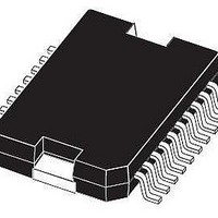
L9949 STMicroelectronics, L9949 Datasheet - Page 3

L9949
Manufacturer Part Number
L9949
Description
IC DRIVER DOOR ACTUATOR PWRSO-20
Manufacturer
STMicroelectronics
Type
Door Actuator Driverr
Datasheet
1.L9949TR.pdf
(20 pages)
Specifications of L9949
Applications
Automotive
Current - Supply
7mA
Voltage - Supply
7 V ~ 28 V
Operating Temperature
-40°C ~ 150°C
Mounting Type
Surface Mount
Package / Case
PowerSO-20 Exposed Bottom Pad
Product
Half-Bridge Drivers
Supply Current
20 mA
Mounting Style
SMD/SMT
Lead Free Status / RoHS Status
Lead free / RoHS Compliant
Available stocks
Company
Part Number
Manufacturer
Quantity
Price
Part Number:
L9949TR
Manufacturer:
ST
Quantity:
20 000
Temperature Warning and Thermal Shutdown
When the junction temperature rises above T
If the junction temperature increases above the second threshold T
the power DMOS transistors of the output stages are switched off to protect the device. In order to reactivate
the output stages the junction temperature must decrease below T
has to be cleared by the microcontroller.
Open Load Detection
The open load detection monitors the voltage drop of current sense resistors in each highside and lowside driver
of the output stage. The output signal of an open load comparator has to be valid for at least 0.5 ms (t
set the open load bit (bit 1-11) in the status register 1.
Over Load Detection
In the case of an overcurrent condition an overcurrent flag (bit 1-11) is set in the status register 0 in the same
way as open load detection. If the overcurrent signal is valid for at least t
and the corresponding driver is switched off to reduce the power dissipation and to protect the integrated circuit.
The microcontroller has to clear the status bits to reactivate the corresponding driver.
Current monitor
The current monitor output sources a current image at the current monitor output which has a fixed ratio (1/
10000) of the instantaneous current of the selected highside driver. The bits 12 and 13 of the Input Data register
controls which of the outputs OUT1, OUT2 and OUT6 will be multiplexed to the current monitor output. The cur-
rent monitor output allows a more precise analyse of the actual state of the load rather than the detection of an
open- or overload condition. For example this can be used to detect the motor state (free-running, loaded or
blocked) or the temperature of the heating element.
Figure 1. Pin Connection (Top view)
OUT3
OUT4
OUT5
OUT1
GND
GND
CLK
VS
VS
DI
1
2
3
4
5
6
7
8
9
10
j TW
D99AT455Amod
a temperature warning flag is set and is available via the SPI.
j SD
j SD
20
19
18
17
16
15
14
13
12
11
, the thermal shutdown bit will be set and
- T
ISC
j SD HYS
= 10µs, the overcurrent flag is set
GND
OUT6
VS
DO
CM
VCC
CSN
VS
OUT2
GND
and the thermal shutdown bit
L9949
dOL
3/20
) to


