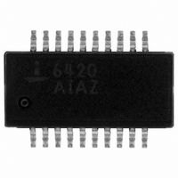
ISL6420AIAZ-TK Intersil, ISL6420AIAZ-TK Datasheet - Page 14

ISL6420AIAZ-TK
Manufacturer Part Number
ISL6420AIAZ-TK
Description
IC CTRLR PWM SYNC BUCK 20-QSOP
Manufacturer
Intersil
Specifications of ISL6420AIAZ-TK
Pwm Type
Voltage Mode
Number Of Outputs
1
Frequency - Max
1.4MHz
Duty Cycle
100%
Voltage - Supply
4.5 V ~ 28 V
Buck
Yes
Boost
No
Flyback
No
Inverting
No
Doubler
No
Divider
No
Cuk
No
Isolated
No
Operating Temperature
-40°C ~ 85°C
Package / Case
20-QSOP
Frequency-max
1.4MHz
Lead Free Status / RoHS Status
Lead free / RoHS Compliant
Other names
ISL6420AIAZ-TKTR
Available stocks
Company
Part Number
Manufacturer
Quantity
Price
Company:
Part Number:
ISL6420AIAZ-TK
Manufacturer:
Intersil
Quantity:
2 400
Undervoltage
If the voltage on the FB pin is less than 15% of the reference
voltage for 8 consecutive PWM cycles, then the circuit enters
into soft-start hiccup mode. This mode is identical to the
overcurrent hiccup mode.
Overvoltage Protection
If the voltage on the FB pin exceeds the reference voltage by
15%, the lower gate driver is turned on continuously to
discharge the output voltage. If the overvoltage condition
continues for 32 consecutive PWM cycles, then the chip is
turned off with the gate drivers three-stated. The voltage on
the FB pin will fall and reach the 15% undervoltage
threshold. After 8 clock cycles, the chip will enter soft-start
hiccup mode. This mode is identical to the overcurrent
hiccup mode.
Gate Control Logic
The gate control logic translates generated PWM control
signals into the MOSFET gate drive signals providing
necessary amplification, level shifting and shoot-through
protection. Also, it has functions that help optimize the IC
performance over a wide range of operational conditions.
Since MOSFET switching time can vary dramatically from
type to type and with the input voltage, the gate control logic
provides adaptive dead time by monitoring the gate-to-
source voltages of both upper and lower MOSFETs. The
lower MOSFET is not turned on until the gate-to-source
voltage of the upper MOSFET has decreased to less than
approximately 1V. Similarly, the upper MOSFET is not turned
on until the gate-to-source voltage of the lower MOSFET has
decreased to less than approximately 1V. This allows a wide
variety of upper and lower MOSFETs to be used without a
concern for simultaneous conduction, or shoot-through.
Startup into Pre-Biased Load
The ISL6420A is designed to power up into a pre-biased
load. This is achieved by transitioning from Diode Emulation
mode to a Forced Continuous Conduction mode during
startup. The lower gate turns ON for a short period of time
and the voltage on the phase pin is sensed. When this goes
negative the lower gate is turned OFF and remains OFF till
the next cycle. As a result the inductor current will not go
negative during soft-start and thus will not discharge the pre-
biased load. The waveform for this condition is shown below.
14
ISL6420A
Application Guidelines
Layout Considerations
As in any high frequency switching converter, layout is very
important. Switching current from one power device to
another can generate voltage transients across the
impedances of the interconnecting bond wires and circuit
traces. These interconnecting impedances should be
minimized by using wide, short printed circuit traces. The
critical components should be located as close together as
possible using ground plane construction or single point
grounding.
FIGURE 14. PRINTED CIRCUIT BOARD POWER AND
ISL6420A
FIGURE 13. PREBIASED OUTPUT AT 25mA LOAD
UGATE
PHASE
LGATE
V
GND
IN
GROUND PLANES OR ISLANDS
= 12V, V
OUT
= 3.3V at 25mA LOAD
V
Q2
Q1
RETURN
IN
D2
C
IN
L
O
C
O
October 13, 2005
V
OUT
FN9169.1


