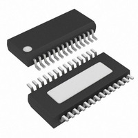
MAX8538EEI+ Maxim Integrated Products, MAX8538EEI+ Datasheet - Page 18

MAX8538EEI+
Manufacturer Part Number
MAX8538EEI+
Description
IC CNTRLR BUCK DUAL 28-QSOP
Manufacturer
Maxim Integrated Products
Datasheet
1.MAX8538EEI.pdf
(23 pages)
Specifications of MAX8538EEI+
Applications
Controller, DDR
Voltage - Input
4.5 ~ 23 V
Number Of Outputs
2
Voltage - Output
0.8 ~ 3.6 V
Operating Temperature
0°C ~ 85°C
Mounting Type
Surface Mount
Package / Case
28-QSOP
Output Voltage
0.8 V to 3.6 V
Output Current
30 A
Input Voltage
4.5 V to 23 V
Mounting Style
SMD/SMT
Maximum Operating Temperature
+ 85 C
Minimum Operating Temperature
- 40 C
Case
SSOP
Dc
05+
Lead Free Status / RoHS Status
Lead free / RoHS Compliant
Dual-Synchronous Buck Controllers for Point-of-
Load, Tracking, and DDR Memory Power Supplies
When the output capacitor is composed of paralleling n
number of the same capacitors, then:
Thus, the resulting f
gle capacitor.
The total closed-loop gain must be equal to unity at the
crossover frequency, where the crossover frequency is
less than or equal to 1/5th the switching frequency (f
So the loop-gain equation at the crossover frequency is:
where G
G
The loop compensation is affected by the choice of out-
put filter capacitor due to the position of its ESR-zero fre-
quency with respect to the desired closed-loop crossover
frequency. Ceramic capacitors are used for higher
switching frequencies (above 750kHz) and have low
capacitance and low ESR; therefore, the ESR-zero fre-
quency is higher than the closed-loop crossover frequen-
cy. Electrolytic capacitors (e.g., tantalum, solid polymer,
and OS-CON) are needed for lower switching frequen-
cies and have high capacitance and higher ESR; there-
fore, the ESR-zero frequency is lower than the
closed-loop crossover frequency. Thus, the compensa-
tion design procedures are separated into two cases:
Case 1: Crossover frequency is less than the output-
capacitor ESR-zero (f
The modulator gain at f
Since the crossover frequency is lower than the output
capacitor ESR-zero frequency and higher than the LC
double-pole frequency, the error-amplifier gain must
have a +1 slope at f
of the LC double pole, the loop crosses over at the
desired -1 slope.
18
and
MOD(FC)
______________________________________________________________________________________
G
MOD DC
EA(FC)
G
is the power-modulator gain at f
MOD(FC)
(
f
Z ESR
)
C
R
_
G
=
ESR
O
is the error-amplifier gain at f
EA(FC)
V
f
=
P LC
RAMP
V
= G
C
Z_ESR
n
_
=
=
IN
so that, together with the -2 slope
C
R
×
2
f
C
C
ESR EACH
MOD(DC)
π
x G
< f
=
C
is:
,
≤ f
×
where V
EACH
2
is the same as that of a sin-
Z_ESR
_
n
MOD(FC)
π
S
R
/ 5
L C
ESR
1
1
x (f
).
O
RAMP
×
P_LC
= 1
C
O
=
/ f
1
C
C
V typ
.
)
2
(
C
)
, and
S
):
The error amplifier has a dominant pole at a very low
frequency (~0Hz), and two additional zeros and two
additional poles as indicated by the equations below
and illustrated in Figure 6:
Note that f
converter closed-loop crossover frequency, f
when the error-amplifier gain has +1 slope, between
f
meet the requirement below:
The gain of the error amplifier between f
f
This gain is set by the ratio of R4/R1, where R1 is calcu-
lated in the Output Voltage Setting section. Thus:
where f
Due to the underdamped (Q > 1) nature of the output
LC double pole, the first error-amplifier zero frequency
must be set less than the LC double-pole frequency in
order to provide adequate phase boost. Set the error-
amplifier first zero, f
frequency. Hence:
Set the error amplifier f
to half the switching frequency. The error-amplifier gain
between f
and is equal to:
where R
The value of R3 can then be calculated as:
Now we can calculate the value of C1 as:
and C3 as:
Z2_EA
Z2_EA
R
I
G
f
= R4 x f
P3_EA
EA
is:
and f
Z2_EA
I
G
C3 = C2 / ((2π x C2 x R4 x f
(f
= R1 x R3 / (R1 + R3). Then:
P2_EA
R4 = R1 x f
Z1_EA
EA
f
Z2_EA
Z2_EA
= 1 / (2π x R4 x (C2 x C3 / (C2 + C3)))
P2_EA
(f
P_LC
= f
R4 x f
Z1_EA
C1 = 1 / (2π x R3 x f
f
f
Z1_EA
P2_EA
G
f
C2 = 2 / (π x R4 x f
Z2_EA
P_LC
R3 = R1 x R
and f
- f
EA(FC)
= 1 / (2π x (R1 + R3) x C1)
and f
. The error-amplifier gain at f
/ (G
Z2_EA
C
Z1_EA
- f
.
= 1 / (2π x R4 x C2)
= 1 / (2π x R3 x C1)
Z2_EA
x G
P3_EA
EA
/ (f
P2_EA
Z2_EA
P2_EA
= 1 / G
) = G
(f
MOD(FC)
C
, at 1/4th the LC double-pole
Z1_EA
x G
/ (f
I
is set by the ratio of R4/R
) x (f
at f
/ (R1 – R
EA(FC)
C
are chosen to have the
MOD(FC)
MOD(FC)
Z_ESR
x G
- f
Z_ESR
/ f
P_LC
Z2_EA
Z_ESR
Z_ESR
MOD(FC)
P3_EA
x f
I
and f
)
Z2_EA
)
)
/ f
) x f
)
P_LC
) - 1)
P3_EA
Z_ESR
)
Z1_EA
/ f
)
C
C
, occur
C
=
) =
equal
must
and
I


