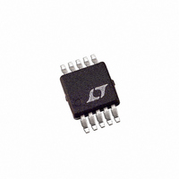
LTC3809EMSE-1 Linear Technology, LTC3809EMSE-1 Datasheet - Page 10

LTC3809EMSE-1
Manufacturer Part Number
LTC3809EMSE-1
Description
IC CTRLR DC/DC SYNC 10-MSOP
Manufacturer
Linear Technology
Type
Step-Down (Buck)r
Datasheet
1.LTC3809EMSE-1PBF.pdf
(24 pages)
Specifications of LTC3809EMSE-1
Internal Switch(s)
No
Synchronous Rectifier
Yes
Number Of Outputs
1
Voltage - Output
0.6 ~ 9.8 V
Current - Output
1A
Frequency - Switching
550kHz
Voltage - Input
2.75 ~ 9.8 V
Operating Temperature
-40°C ~ 85°C
Mounting Type
Surface Mount
Package / Case
10-MSOP Exposed Pad, 10-HMSOP, 10-eMSOP
Lead Free Status / RoHS Status
Contains lead / RoHS non-compliant
Power - Output
-
Available stocks
Company
Part Number
Manufacturer
Quantity
Price
Company:
Part Number:
LTC3809EMSE-1
Manufacturer:
LT
Quantity:
10 000
Company:
Part Number:
LTC3809EMSE-1#PBF
Manufacturer:
Linear Technology
Quantity:
135
LTC3809-1
In sleep mode, much of the internal circuitry is turned off,
reducing the quiescent current that the LTC3809-1 draws.
The load current is supplied by the output capacitor. As
the output voltage decreases, the EAMP increases the
I
SLEEP signal goes low and the controller resumes normal
operation by turning on the external P-channel MOSFET
on the next cycle of the internal oscillator.
When the controller is enabled for Burst Mode or pulse-
skipping operation, the inductor current is not allowed to
reverse. Hence, the controller operates discontinuously.
The reverse current comparator RICMP senses the
drain-to-source voltage of the bottom external N-channel
MOSFET. This MOSFET is turned off just before the inductor
current reaches zero, preventing it from going negative.
In forced continuous operation, the inductor current is
allowed to reverse at light loads or under large transient
conditions. The peak inductor current is determined by the
voltage on the I
on every cycle (constant frequency) regardless of the I
pin voltage. In this mode, the effi ciency at light loads is
lower than in Burst Mode operation. However, continuous
mode has the advantages of lower output ripple and no
noise at audio frequencies.
When the MODE pin is set to the V
operates in PWM pulse-skipping mode at light loads. In
this mode, the current comparator ICMP may remain
tripped for several cycles and force the external P-channel
MOSFET to stay off for the same number of cycles. The
inductor current is not allowed to reverse (discontinuous
operation). This mode, like forced continuous operation,
exhibits low output ripple as well as low audible noise
and reduced RF interference as compared to Burst Mode
operation. However, it provides low current effi ciency
higher than forced continuous mode, but not nearly as
OPERATION
10
TH
voltage. When the I
TH
pin. The P-channel MOSFET is turned
(Refer to Functional Diagram)
TH
voltage reaches 0.925V, the
FB
Pin, the LTC3809-1
TH
high as Burst Mode operation. During start-up or an
undervoltage condition (V
operates in pulse-skipping mode (no current reversal
allowed), regardless of the state of the MODE pin.
Short-Circuit and Current Limit Protection
The LTC3809-1 monitors the voltage drop ΔV
the GND and SW pins) across the external N-channel
MOSFET with the short-circuit current limit comparator.
The allowed voltage is determined by:
where A is a constant determined by the state of the IPRG
pin. Floating the IPRG pin selects A = 1; tying IPRG to V
selects A = 5/3; tying IPRG to GND selects A = 2/3.
The inductor current limit for short-circuit protection is
determined by ΔV
external N-channel MOSFET:
Once the inductor current exceeds I
comparator will shut off the external P-channel MOSFET
until the inductor current drops below I
Output Overvoltage Protection
As further protection, the overvoltage comparator (OVP)
guards against transient overshoots, as well as other more
serious conditions that may overvoltage the output. When
the feedback voltage on the V
above the reference voltage of 0.6V, the external P-channel
MOSFET is turned off and the N-channel MOSFET is turned
on until the overvoltage is cleared.
ΔV
I
SC
SC(MAX)
=
Δ
R
V
SC MAX
DS ON
= A • 90mV
(
(
)
SC(MAX)
)
FB
and the on-resistance of the
≤ 0.54V), the LTC3809-1
FB
pin has risen 13.33%
SC
, the short current
SC
.
SC
(between
38091fc
IN


