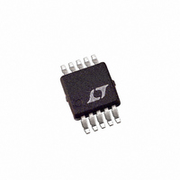
LTC3809EMSE-1 Linear Technology, LTC3809EMSE-1 Datasheet - Page 17

LTC3809EMSE-1
Manufacturer Part Number
LTC3809EMSE-1
Description
IC CTRLR DC/DC SYNC 10-MSOP
Manufacturer
Linear Technology
Type
Step-Down (Buck)r
Datasheet
1.LTC3809EMSE-1PBF.pdf
(24 pages)
Specifications of LTC3809EMSE-1
Internal Switch(s)
No
Synchronous Rectifier
Yes
Number Of Outputs
1
Voltage - Output
0.6 ~ 9.8 V
Current - Output
1A
Frequency - Switching
550kHz
Voltage - Input
2.75 ~ 9.8 V
Operating Temperature
-40°C ~ 85°C
Mounting Type
Surface Mount
Package / Case
10-MSOP Exposed Pad, 10-HMSOP, 10-eMSOP
Lead Free Status / RoHS Status
Contains lead / RoHS non-compliant
Power - Output
-
Available stocks
Company
Part Number
Manufacturer
Quantity
Price
Company:
Part Number:
LTC3809EMSE-1
Manufacturer:
LT
Quantity:
10 000
Company:
Part Number:
LTC3809EMSE-1#PBF
Manufacturer:
Linear Technology
Quantity:
135
APPLICATIONS INFORMATION
For coincident tracking (V
V
tracking function of TRACK/SS pin.
The internal current source (1μA), which is for external
soft-start, will cause a tracking error at V
if a 59k resistor is chosen for R
about 10μA (600mV/59k). In this case, the 1μA internal
current source will cause about 10% (1μA/10μA • 100%)
tracking error, which is about 60mV (600mV • 10%)
referred to V
If a better tracking accuracy is required, the value of R
should be reduced.
Table 1 summarizes the different states in which the
TRACK/SS can be used.
Table 1. The States of the TRACK/SS Pin
TRACK/SS Pin
Capacitor C
V
Resistor Divider
IN
X
R
should always be greater than V
TA
= R
SS
A
, R
FB
TB
. This is acceptable for most applications.
= R
B
(5b) Coincident Tracking
FREQUENCY
External Soft-Start
Internal Soft-Start
V
OUT
OUT
Tracking an External Voltage V
= V
Figure 5b and 5c. Two Different Modes of Output Voltage Tracking
TIME
TA
, the R
X
during start-up),
OUT
OUT
TA
when using the
current will be
. For example,
V
V
X
OUT
X
TA
Auxiliary Winding Control Using the MODE Pin
The MODE pin can be used as an auxiliary feedback to
provide a means of regulating a fl yback winding output.
When this pin drops below its ground-referenced 0.4V
threshold, continuous mode operation is forced.
During continuous mode, current fl ows continuously in
the transformer primary side. The auxiliary winding draws
current only when the bottom synchronous N-channel
MOSFET is on. When primary load currents are low and/
or the V
MOSFET may not be on for a suffi cient amount of time to
transfer power from the output capacitor to the auxiliary
load. Forced continuous operation will support an auxiliary
winding as long as there is a suffi cient synchronous
MOSFET duty factor. The MODE input pin removes
the requirement that power must be drawn from the
transformer primary side in order to extract power from
the auxiliary winding. With the loop in continuous mode,
the auxiliary output may nominally be loaded without
regard to the primary output load.
IN
/V
(5c) Ratiometric Tracking
OUT
ratio is close to unity, the synchronous
TIME
38091 F05b,c
LTC3809-1
V
V
X
OUT
17
38091fc


