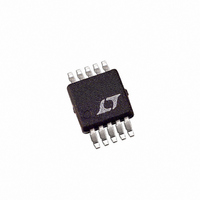
LTC3809EMSE-1 Linear Technology, LTC3809EMSE-1 Datasheet - Page 11

LTC3809EMSE-1
Manufacturer Part Number
LTC3809EMSE-1
Description
IC CTRLR DC/DC SYNC 10-MSOP
Manufacturer
Linear Technology
Type
Step-Down (Buck)r
Datasheet
1.LTC3809EMSE-1PBF.pdf
(24 pages)
Specifications of LTC3809EMSE-1
Internal Switch(s)
No
Synchronous Rectifier
Yes
Number Of Outputs
1
Voltage - Output
0.6 ~ 9.8 V
Current - Output
1A
Frequency - Switching
550kHz
Voltage - Input
2.75 ~ 9.8 V
Operating Temperature
-40°C ~ 85°C
Mounting Type
Surface Mount
Package / Case
10-MSOP Exposed Pad, 10-HMSOP, 10-eMSOP
Lead Free Status / RoHS Status
Contains lead / RoHS non-compliant
Power - Output
-
Available stocks
Company
Part Number
Manufacturer
Quantity
Price
Company:
Part Number:
LTC3809EMSE-1
Manufacturer:
LT
Quantity:
10 000
Company:
Part Number:
LTC3809EMSE-1#PBF
Manufacturer:
Linear Technology
Quantity:
135
OPERATION
Dropout Operation
When the input supply voltage (V
voltage, the rate of change of the inductor current while the
external P-channel MOSFET is on (ON cycle) decreases.
This reduction means that the P-channel MOSFET will
remain on for more than one oscillator cycle if the inductor
current has not ramped up to the threshold set by the
EAMP on the I
voltage will eventually cause the P-channel MOSFET to be
turned on 100%; i.e., DC. The output voltage will then be
determined by the input voltage minus the voltage drop
across the P-channel MOSFET and the inductor.
Undervoltage Lockout
To prevent operation of the P-channel MOSFET below
safe input voltage levels, an undervoltage lockout is
incorporated in the LTC3809-1. When the input supply
voltage (V
N-channel MOSFETs and all internal circuits are turned
off except for the undervoltage block, which draws only
a few microamperes.
Peak Current Sense Voltage Selection
and Slope Compensation (IPRG Pin)
When the LTC3809-1 controller is operating below 20%
duty cycle, the peak current sense voltage (between the
V
MOSFET is determined by:
IN
Δ
and SW pins) allowed across the external P-channel
V
SENSE MAX
IN
(
) drops below 2.25V, the external P- and
TH
pin. Further reduction in the input supply
)
=
A
•
(Refer to Functional Diagram)
V
ITH
10
– . 0 7
IN
V
) approaches the output
where A is a constant determined by the state of the IPRG
pin. Floating the IPRG pin selects A = 1; tying IPRG to
V
The maximum value of V
the maximum sense voltage allowed across the external
P-channel MOSFET is 125mV, 85mV or 204mV for the
three respective states of the IPRG pin.
However, once the controller’s duty cycle exceeds 20%,
slope compensation begins and effectively reduces the
peak sense voltage by a scale factor (SF) given by the
curve in Figure 1.
The peak inductor current is determined by the peak sense
voltage and the on-resistance of the external P-channel
MOSFET:
IN
I
PK
selects A = 5/3; tying IPRG to GND selects A = 2/3.
=
Figure 1. Maximum Peak Current vs Duty Cycle
Δ
V
R
SENSE MAX
110
100
90
80
70
60
50
40
30
20
10
DS ON
0
0
(
10
(
)
20
)
30
DUTY CYCLE (%)
ITH
40
is typically about 1.98V, so
50
60
70
LTC3809-1
80
38091 F01
90
100
11
38091fc


