AD7940-DBRD Analog Devices Inc, AD7940-DBRD Datasheet - Page 14
AD7940-DBRD
Manufacturer Part Number
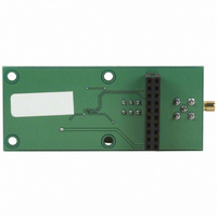
AD7940-DBRD
Description
BOARD EVAL FOR AD7940 STAMP SPI
Manufacturer
Analog Devices Inc
Datasheet
1.AD7940BRJZ-REEL7.pdf
(20 pages)
Specifications of AD7940-DBRD
Number Of Adc's
1
Number Of Bits
14
Sampling Rate (per Second)
100k
Data Interface
Serial
Inputs Per Adc
1 Single Ended
Input Range
0 ~ Vdd
Power (typ) @ Conditions
17mW @ 100kSPS & 5 V
Voltage Supply Source
Single Supply
Operating Temperature
-40°C ~ 85°C
Utilized Ic / Part
AD7940
Lead Free Status / RoHS Status
Lead free / RoHS non-compliant


AD7940
POWER-DOWN MODE
This mode is intended for use in applications where slower
throughput rates are required. Either the ADC is powered down
between each conversion, or a series of conversions may be
performed at a high throughput rate, and then the ADC is pow-
ered down for a relatively long duration between these bursts of
several conversions. When the AD7940 is in power-down, all
analog circuitry is powered down.
To enter power-down, the conversion process must be inter-
rupted by bringing CS high anywhere after the second falling
edge of SCLK and before the 10th falling edge of SCLK as
shown in Figure 17. Once CS has been brought high in this
window of SCLKs, the part will enter power-down, the
conversion that was initiated by the falling edge of CS will be
terminated, and SDATA will go back into three-state. If CS is
brought high before the second SCLK falling edge, the part will
remain in normal mode and will not power down. This will
avoid accidental power-down due to glitches on the CS line.
SDATA
SCLK
CS
1
THE PART BEGINS
TO POWER UP
SDATA
SCLK
CS
INVALID DATA
10
1
t
POWER UP
2
Figure 17. Entering Power-Down Mode
Figure 18. Exiting Power-Down Mode
16
Rev. 0 | Page 14 of 20
In order to exit this mode of operation and power up the
AD7940 again, a dummy conversion is performed. On the fal-
ling edge of CS , the device will begin to power up and will
continue to power up as long as CS is held low until after the
falling edge of the 10th SCLK. The device will be fully powered
up once at least 16 SCLKs (or approximately 6 µs) have elapsed
and valid data will result from the next conversion as shown in
Figure 18. If CS is brought high before the 10th falling edge of
SCLK, regardless of the SCLK frequency, the AD7940 will go
back into power-down again. This avoids accidental power-up
due to glitches on the CS line or an inadvertent burst of 8 SCLK
cycles while CS is low. So although the device may begin to
power-up on the falling edge of CS , it will power down again on
the rising edge of CS as long as it occurs before the 10th SCLK
falling edge.
10
1
THE PART IS FULLY POWERED
UP WITH V
THREE-STATE
IN
FULLY ACQUIRED
VALID DATA
16
16
Related parts for AD7940-DBRD
Image
Part Number
Description
Manufacturer
Datasheet
Request
R

Part Number:
Description:
±1.7g Dual-Axis IMEMS Accelerometer Evaluation Board
Manufacturer:
Analog Devices Inc
Datasheet:

Part Number:
Description:
Inertial Sensor Evaluation System
Manufacturer:
Analog Devices Inc
Datasheet:
Part Number:
Description:
Manufacturer:
Analog Devices Inc
Datasheet:
Part Number:
Description:
Manufacturer:
Analog Devices Inc
Datasheet:
Part Number:
Description:
Manufacturer:
Analog Devices Inc
Datasheet:
Part Number:
Description:
Manufacturer:
Analog Devices Inc
Datasheet:
Part Number:
Description:
Manufacturer:
Analog Devices Inc
Datasheet:
Part Number:
Description:
Manufacturer:
Analog Devices Inc
Datasheet:
Part Number:
Description:
Manufacturer:
Analog Devices Inc
Datasheet:
Part Number:
Description:
Manufacturer:
Analog Devices Inc
Datasheet:
Part Number:
Description:
Manufacturer:
Analog Devices Inc
Datasheet:
Part Number:
Description:
Manufacturer:
Analog Devices Inc
Datasheet:
Part Number:
Description:
Manufacturer:
Analog Devices Inc
Datasheet: