CDB5532U Cirrus Logic Inc, CDB5532U Datasheet - Page 4
CDB5532U
Manufacturer Part Number
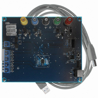
CDB5532U
Description
BOARD EVAL FOR CS5532U ADC
Manufacturer
Cirrus Logic Inc
Specifications of CDB5532U
Number Of Adc's
2
Number Of Bits
24
Sampling Rate (per Second)
3.84k
Data Interface
Serial
Inputs Per Adc
1 Differential
Input Range
±2.5 V
Power (typ) @ Conditions
35mW @ 3.84kSPS
Voltage Supply Source
Analog and Digital, Dual ±
Operating Temperature
-40°C ~ 85°C
Utilized Ic / Part
CS5532
Description/function
Audio DSPs
Operating Supply Voltage
5 V
Product
Audio Modules
For Use With/related Products
C8051F320
Lead Free Status / RoHS Status
Contains lead / RoHS non-compliant
Lead Free Status / RoHS Status
Lead free / RoHS Compliant, Contains lead / RoHS non-compliant
Other names
598-1159


1.2.2
Figure 8 illustrates the schematic of the digital section. It contains the microcontroller, USB interface, EE-
PROM, JTAG header, reset circuitry, and an external interface header. The microcontroller interfaces the
SPI
that the SCLK and SDI signals are level shifted to support both +3.3 V and +5 V digital operation.
The microcontroller EEPROM is used to store firmware. An external interface header, J19, is provided to
allow the CDB5532U to be interfaced with an external microcontroller. To use this serial interface, the
0 ohm resistors R9, R10, R23, and R27 should be removed to disconnect the on-board microcontroller
from the serial interface.
1.2.3
Figure 9 illustrates the power supply connections to the evaluation board. VA+ supplies the positive ana-
log supply for the CS5532 and the LT1019 reference. Header J14 allows the VA+ supply to be sourced
from either the VA+ binding post (J2), or from the +5 V binding post (J3). VA- supplies the negative analog
supply for the analog section. Header J13 allows the VA- supply to be sourced from either the VA- binding
post (J1), or connected to the board ground. Note that the VA- supply should be connected to ground
when powering the CDB5532U from a single +5 V analog supply. VD+ supplies the digital section of the
ADC and level shifters. Header J15 allows the VD+ supply to be sourced from the VD+ binding post (J5),
the +5 V binding post (J3), or the regulated +3.3 V supply derived from the microcontroller. The +5 V bind-
ing post supplies the microcontrollers internal regulator.
4
™
and MICROWIRE
Digital Section
Power Supply Section
™
compatible serial port of the CS5532 with the USB connection to the PC. Note
Reference
Reference
Table 1. Voltage Reference Selection for VREF+
Table 2. Voltage Reference Selection for VREF-
LT1019
VREF+
VREF-
GND
VA+
VA-
LT1019 Reference
Reference Source
Reference Source
Selects on-Board
Selects Negative
Selects External
Selects External
Selects Positive
Analog Power
Analog Power
Selects Board
Description
Description
(5ppm/
Supply
Supply
(J12)
(J12)
Gnd
°
C)
LT1019
LT1019
LT1019
REF+
REF+
REF+
REF-
REF-
REF-
GND
GND
GND
VA+
VA+
VA+
VA-
VA-
VA-
O
O
O
O
O
O
O
O
O
O
O
O
O
O
O
O
O
O
J17
J18
O VREF+
O VREF+
O VREF+
O VREF+
O VREF+
O VREF+
O VREF+
O VREF+
O VREF+
O VREF-
O VREF-
O VREF-
O VREF-
O VREF-
O VREF-
O VREF-
O VREF-
O VREF-
CDB5532U
DS807DB1
Related parts for CDB5532U
Image
Part Number
Description
Manufacturer
Datasheet
Request
R

Part Number:
Description:
Development Kit
Manufacturer:
Cirrus Logic Inc
Datasheet:
Part Number:
Description:
Development Kit
Manufacturer:
Cirrus Logic Inc
Datasheet:


Part Number:
Description:
High-efficiency PFC + Fluorescent Lamp Driver Reference Design
Manufacturer:
Cirrus Logic Inc
Datasheet:
Part Number:
Description:
Development Kit
Manufacturer:
Cirrus Logic Inc
Datasheet:
Part Number:
Description:
Development Kit
Manufacturer:
Cirrus Logic Inc
Datasheet:

Part Number:
Description:
Development Kit
Manufacturer:
Cirrus Logic Inc
Datasheet:
Part Number:
Description:
Development Kit
Manufacturer:
Cirrus Logic Inc
Datasheet:
Part Number:
Description:
Development Kit
Manufacturer:
Cirrus Logic Inc
Datasheet:
Part Number:
Description:
Development Kit
Manufacturer:
Cirrus Logic Inc
Datasheet:

Part Number:
Description:
EVALUATION BOARD FOR CS8427
Manufacturer:
Cirrus Logic Inc
Datasheet:

Part Number:
Description:
BOARD EVAL FOR CS8416 RCVR
Manufacturer:
Cirrus Logic Inc
Datasheet:

Part Number:
Description:
EVALUATION BOARD FOR CS8420
Manufacturer:
Cirrus Logic Inc
Datasheet:

Part Number:
Description:
KIT DEVELOPMENT EP9315 ARM9
Manufacturer:
Cirrus Logic Inc
Datasheet:

Part Number:
Description:
KIT DEVELOPMENT EP9302 ARM9
Manufacturer:
Cirrus Logic Inc
Datasheet: