NCP3065SOBSTGEVB ON Semiconductor, NCP3065SOBSTGEVB Datasheet - Page 2
NCP3065SOBSTGEVB
Manufacturer Part Number
NCP3065SOBSTGEVB
Description
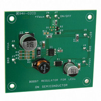
EVAL BOARD FOR NCP3065SOBSTG
Manufacturer
ON Semiconductor
Datasheets
1.NCP3065DR2G.pdf
(18 pages)
2.NCP3065SOBSTGEVB.pdf
(1 pages)
3.NCP3065SOBSTGEVB.pdf
(18 pages)
Specifications of NCP3065SOBSTGEVB
Design Resources
NCP3065 Boost Eval Board BOM NCP3065SOBSTGEVB Gerber Files NCP3065 Boost Eval Board Schematic
Current - Output / Channel
350mA
Outputs And Type
1, Non-Isolated
Voltage - Output
20 V
Voltage - Input
12V
Utilized Ic / Part
NCP3065
Core Chip
NCP3065
Topology
Buck-Boost
No. Of Outputs
1
Dimming Control Type
PWM
Development Tool Type
Hardware - Eval/Demo Board
Leaded Process Compatible
Yes
Mcu Supported Families
NCP3065
Rohs Compliant
Yes
Lead Free Status / RoHS Status
Lead free / RoHS Compliant
Features
-
Lead Free Status / Rohs Status
Lead free / RoHS Compliant
For Use With/related Products
NCP3065SOBSTG
Other names
NCP3065SOBSTGEVBOS


smaller and less expensive. Alternatively, the circuit could
be run at lower frequency with the same inductor value
which improves the efficiency and expands the output
voltage range. Equation 2 is used to calculate the capacitor
size based on the amount of LED ripple.
No Output Capacitor Operation
focuses on the control of the current through the load, not the
voltage across it. The switching frequency of the NCP3065
is in the range of 100 kHz − 300 kHz which is much higher
than the human eye can detect. This allows us to relax the
ripple current specification to allow higher peak to peak
values. This is achieved by configuring the NCP3065 in a
continuous conduction buck configuration with low peak to
peak ripple thus eliminating the need for an output filter
capacitor. The important design parameter is to keep the
peak current below the maximum current rating of the LED.
Using 15% peak−to−peak ripple results in a good
compromise between achieving max average output current
without exceeding the maximum limit. This saves space and
reduces part count for applications that require a compact
footprint. For the common LED currents such as the
350 mA, 700 mA, 1000 mA we setup inductor ripple
current to the $52.5 mA, $105 mA, $150 mA. With
respect these requirements we are able to select inductor
value (Equation 1).
A constant current buck regulator such as the NCP3065
L +
V
IN
DI
* V
MAX
OUT
T
ON
(eq. 1)
http://onsemi.com
2
Output Capacitor
its value, ESR and ripple current.
Current Feedback Loop
for the regulator is taken by sensing the voltage drop across
the sensing resistor R
(R10 & C5) between the sense resistor and the feedback pin
improves converter transient response. The low feedback
reference voltage of 235 mV allows the use of low power
and lower cost sense resistor. Equation 3 calculates the sense
resistor value.
When you choose output capacitor we have to think about
To drive LEDs in a constant current mode, the feedback
LED current
(mA)
1000
350
700
C
I
OUT
OUT
+
+
R
V
DV * 8 * f
sense
REF
DI
12
+
, see Figures 2 or 8. The RC circuit
0.235 V
680
330
220
+
R
Sensing resistor value
sense
8 * L * f
V
IN
* (1 * D) * D
[ A ]
(mW)
2
* DV
OUT
1/4W
1/4W
1/4W
(eq. 2)
(eq. 3)
Related parts for NCP3065SOBSTGEVB
Image
Part Number
Description
Manufacturer
Datasheet
Request
R

Part Number:
Description:
Up to 1.5 A Constant Current Switching Regulator for LEDs
Manufacturer:
ON Semiconductor
Datasheet:

Part Number:
Description:
EVAL BOARD FOR NCP3065SOBCKG
Manufacturer:
ON Semiconductor
Datasheet:

Part Number:
Description:
EVAL BOARD FOR NCP30653ABCKG
Manufacturer:
ON Semiconductor
Datasheet:
Part Number:
Description:
ON Semiconductor [VOLTAGE REGULATOR]
Manufacturer:
ON Semiconductor
Datasheet:
Part Number:
Description:
357-036-542-201 CARDEDGE 36POS DL .156 BLK LOPRO
Manufacturer:
ON Semiconductor
Datasheet:
Part Number:
Description:
357-036-542-201 CARDEDGE 36POS DL .156 BLK LOPRO
Manufacturer:
ON Semiconductor
Datasheet:
Part Number:
Description:
357-036-542-201 CARDEDGE 36POS DL .156 BLK LOPRO
Manufacturer:
ON Semiconductor
Datasheet:
Part Number:
Description:
357-036-542-201 CARDEDGE 36POS DL .156 BLK LOPRO
Manufacturer:
ON Semiconductor
Datasheet:
Part Number:
Description:
357-036-542-201 CARDEDGE 36POS DL .156 BLK LOPRO
Manufacturer:
ON Semiconductor
Datasheet:
Part Number:
Description:
357-036-542-201 CARDEDGE 36POS DL .156 BLK LOPRO
Manufacturer:
ON Semiconductor
Datasheet:
Part Number:
Description:
357-036-542-201 CARDEDGE 36POS DL .156 BLK LOPRO
Manufacturer:
ON Semiconductor
Datasheet:
Part Number:
Description:
357-036-542-201 CARDEDGE 36POS DL .156 BLK LOPRO
Manufacturer:
ON Semiconductor
Datasheet:
Part Number:
Description:
357-036-542-201 CARDEDGE 36POS DL .156 BLK LOPRO
Manufacturer:
ON Semiconductor
Datasheet:
Part Number:
Description:
357-036-542-201 CARDEDGE 36POS DL .156 BLK LOPRO
Manufacturer:
ON Semiconductor
Datasheet: