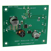
NCP3065SOBSTGEVB ON Semiconductor, NCP3065SOBSTGEVB Datasheet - Page 3

NCP3065SOBSTGEVB
Manufacturer Part Number
NCP3065SOBSTGEVB
Description
EVAL BOARD FOR NCP3065SOBSTG
Manufacturer
ON Semiconductor
Datasheets
1.NCP3065DR2G.pdf
(18 pages)
2.NCP3065SOBSTGEVB.pdf
(1 pages)
3.NCP3065SOBSTGEVB.pdf
(18 pages)
Specifications of NCP3065SOBSTGEVB
Design Resources
NCP3065 Boost Eval Board BOM NCP3065SOBSTGEVB Gerber Files NCP3065 Boost Eval Board Schematic
Current - Output / Channel
350mA
Outputs And Type
1, Non-Isolated
Voltage - Output
20 V
Voltage - Input
12V
Utilized Ic / Part
NCP3065
Core Chip
NCP3065
Topology
Buck-Boost
No. Of Outputs
1
Dimming Control Type
PWM
Development Tool Type
Hardware - Eval/Demo Board
Leaded Process Compatible
Yes
Mcu Supported Families
NCP3065
Rohs Compliant
Yes
Lead Free Status / RoHS Status
Lead free / RoHS Compliant
Features
-
Lead Free Status / Rohs Status
Lead free / RoHS Compliant
For Use With/related Products
NCP3065SOBSTG
Other names
NCP3065SOBSTGEVBOS
Dimming Possibility
(LED) current. The NCP3065 is capable of analog and
digital PWM dimming. For the dimming we have three
possibilities how to create it. We basically use a PWM signal
with variable duty cycle for the managing output current
value. The COMP or IPK pin of the NCP3065 is used to
provide dimming capability. In digital input mode the PWM
input signal inhibits switching of the regulator and reducing
the average current through the LEDs. In analog input mode
a PWM input signal is RC filtered and the resulting voltage
is summed with the feedback voltage thus reduces the
Table 1. COMPONENTS CHANGES FOR DIFFERENT CONFIGURATIONS
NCP3065
The emitted LED light is proportional to average output
LED Driver
BUCK
Comp
GND
Vout
Figure 2. NCP3065 Current Feedback
24 V
12 V
12 V
12 V
24 V
12 V
12 V
12 V
12 V
Application
12 V
DC
DC
DC
DC
DC
AC
AC
AC
AC
AC
10 W LED
1 W LED
3 W LED
5 W LED
1 W LED
3 W LED
5 W LED
5 W LED
15 W
5 W
I = 350 mA
700 mA, 1000 mA
R
sense
10 − 14
10 − 14
10 − 14
21 − 27
21 − 27
14 − 20
14 − 20
14 − 20
14 − 20
21 − 27
V
(V)
http://onsemi.com
IN
3
700 or 1000
700 or 1000
700 or 350
700 or 350
(mA)
1000
I
average current through the LEDs Figure 5. The component
value of the RC filter are dependent on the PWM frequency.
Due to this, the frequency has to be higher. Figure 17
illustrates the linearity of the digital dimming function with
a 200 Hz digital PWM. The dimming frequency range for
digital input mode is basically from 200 Hz to 1 kHz. For
frequencies below 200 Hz the human eye will see the flicker.
The low dimming frequencies are EMI convenient and an
impact to it is small.
uses the COMP pin to perform the dimming function and
Figure 4 show us an example of solution B. The behavior of
the NCP3065 with dimming you can see in Figures 15
and 16 and dimming linearity in the Figure 17. As you can
see in these figures there aren’t any delays in the rise or fall
edges, which give us the required dimming linearity.
350
350
700
350
350
LED
The Figure 3 shows us an example of solution A, which
3.6 or 7.2
7.2 or 3.6
3.6 or 7.2
7.2 or 3.6
3.6
3.6
(V)
V
14
14
14
14
F
(mH)
150
150
150
220
220
220
220
220
220
47
47
47
68
68
47
47
47
47
47
L
C
(mF)
100
100
100
100
100
100
100
100
100
100
OUT
0
0
0
0
0
0
0
0
0
100k/16k
160k
150k
100k
12k
3k3
16k
12k
12k
12k
39k
7k5
7k5
22k
22k
36k
82k
NU
NU
(W)
R8


