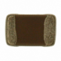
ECJ-2F60J226M Panasonic - ECG, ECJ-2F60J226M Datasheet - Page 16

ECJ-2F60J226M
Manufacturer Part Number
ECJ-2F60J226M
Description
CAP CERAMIC 22UF 6.3V 0805 X6S
Manufacturer
Panasonic - ECG
Series
ECJr
Datasheets
1.ECJ-RVB1H332M.pdf
(6 pages)
2.ECJ-RVB1H332M.pdf
(2 pages)
3.ECJ-RVB1H332M.pdf
(1 pages)
4.ECJ-RVB1H332M.pdf
(3 pages)
5.ECJ-2F60J226M.pdf
(24 pages)
Specifications of ECJ-2F60J226M
Capacitance
22µF
Voltage - Rated
6.3V
Tolerance
±20%
Temperature Coefficient
X6S
Mounting Type
Surface Mount, MLCC
Operating Temperature
-55°C ~ 105°C
Features
Low ESR
Applications
General Purpose
Package / Case
0805 (2012 Metric)
Size / Dimension
0.079" L x 0.049" W (2.00mm x 1.25mm)
Thickness
1.25mm
Lead Free Status / RoHS Status
Lead free / RoHS Compliant
Ratings
-
Lead Spacing
-
Other names
ECJ2F60J226M
PCC2477TR
PCC2477TR
CLASSIFICATION
SUBJECT
3- 5.Post Soldering Cleaning
Note ;
3-4-2. Hand soldering
3-5-1. Cleaning solvent
3-5-2. Cleaning conditions
Hand soldering typically causes significant temperature change, which may induce excessive thermal stresses
inside the Capacitors, resulting in the thermal cracks, etc.
In order to prevent any defects, the following should be observed;
Soldering flux residue may remain on the PC board if cleaned with an inappropriate solvent. This may deteriorate
the electrical characteristics and reliability of the Capacitors.
Inappropriate cleaning conditions such as insufficient cleaning or excessive cleaning may impair the electrical
characteristics and reliability of the Capacitors.
・The temperature of the soldering tips should be controlled with special care.
・The direct contact of soldering tips with the Capacitors and/or terminal electrodes should be avoided.
・Dismounted Capacitors shall not be reused.
(1) Condition 1 (with preheating)
(2) Condition 2 (without preheating)
(1) Insufficient cleaning can lead to:
(a) Soldering :
(b) Preheating:
(c) Temperature of Iron tip: 300℃ max.
(d) Gradual Cooling:
Hand soldering can be performed without preheating, by following the conditions below:
(a) Soldering iron tip shall never directly touch the ceramic dielectrics and terminal electrodes of the
(b) The lands are sufficiently preheated with a soldering iron tip before sliding the soldering iron tip to the
(a) The halogen substance in the residues of the soldering flux to cause the metal of terminal electrodes to
(b) The halogen substance in the residue of the soldering flux on the surface of the Capacitors may change
Recommended profile of Hand Soldering [Ex.]
Preheating
φ
*Rosin-based and non-activated flux is recommended.
The Capacitors shall be preheated so that the “Temperature Gradient” between the devices and the tip
of soldering iron is 150℃ or below.
(The required amount of solder shall be melted in advance on the soldering tip.)
After soldering, the Capacitors shall be cooled gradually at room ambient temperature.
Capacitors.
terminal electrodes of the Capacitor for soldering.
corrode.
resistance values.
1.0mm or below Thread eutectic solder with soldering flux* in the core.
Chip size
Temperature of soldering iron
Wattage
Shape of soldering iron tip
Soldering time with soldering iron
Common Specification ( Precautions for Use)
60 to 120 s
Multilayer Ceramic Chip Capacitor
∆
T
Conditions of Hand soldering without preheating
SPECIFICATIONS
Soldering
3 s max .
0201 to 0805, 0508, 0504
Gradual
cooling
270 °C max.
〈Allowable temperature difference ∆T〉
0508, 0612, 0504
0201 to 1206
φ
20W max.
Condition
3mm max.
3s max.
1210
Size
1206 to 1210 , 0612
250 °C max.
No.
PAGE
DATE
∆T≦ 150 °C
∆T≦ 130 °C
Temp. Tol.
151S-ECJ-SS018E
Apr. 1, 2008
7 of 9


