ECJ-2F60J226M Panasonic - ECG, ECJ-2F60J226M Datasheet - Page 17
ECJ-2F60J226M
Manufacturer Part Number
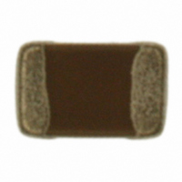
ECJ-2F60J226M
Description
CAP CERAMIC 22UF 6.3V 0805 X6S
Manufacturer
Panasonic - ECG
Series
ECJr
Datasheets
1.ECJ-RVB1H332M.pdf
(6 pages)
2.ECJ-RVB1H332M.pdf
(2 pages)
3.ECJ-RVB1H332M.pdf
(1 pages)
4.ECJ-RVB1H332M.pdf
(3 pages)
5.ECJ-2F60J226M.pdf
(24 pages)
Specifications of ECJ-2F60J226M
Capacitance
22µF
Voltage - Rated
6.3V
Tolerance
±20%
Temperature Coefficient
X6S
Mounting Type
Surface Mount, MLCC
Operating Temperature
-55°C ~ 105°C
Features
Low ESR
Applications
General Purpose
Package / Case
0805 (2012 Metric)
Size / Dimension
0.079" L x 0.049" W (2.00mm x 1.25mm)
Thickness
1.25mm
Lead Free Status / RoHS Status
Lead free / RoHS Compliant
Ratings
-
Lead Spacing
-
Other names
ECJ2F60J226M
PCC2477TR
PCC2477TR


CLASSIFICATION
SUBJECT
3- 6.Inspection Process
3- 7.Protective Coating
3- 8.Dividing/Breaking of PC Boards
Note ;
3-5-3. Contamination of Cleaning solvent
When mounted PC boards are inspected with measuring terminal pins, abnormal and excess mechanical stress
shall not be applied to the PC board or mounted components, to prevent failure or damage to the devices.
(1) Mounted PC boards shall be supported by an adequate number of supporting pins with bend settings of 90 mm
(2) Confirm that the measuring pins have the right tip shape, are equal in height and are set in the correct positions.
When the surface of a PC board on which the Capacitors have been mounted is coated with resin to protect against
moisture and dust, it shall be confirmed that the protective coating which is corrosive or chemically active is not
used, in order that the reliability of the Capacitors in the actual equipment may not be influenced. Coating materials
that expand or shrink also may lead to damage to the Capacitor during the curing process.
(1) Abnormal and excessive mechanical stress such as bending or torsion
(2) Dividing/Breaking of the PC boards shall be done carefully at moderate
(3) Examples of PCB dividing/breaking jigs:
Cleaning with contaminated cleaning solvent may cause the same results as insufficient cleaning due to the high
density of liberated halogen.
PC board
When PC boards are broken or divided, loading points should be close to the jig to minimize the extent of
the bending
span 0.5mm max.
The following figures are for your reference to avoid bending the PC board.
shown below can cause cracking in the Capacitors.
speed by using a jig or apparatus to prevent the Capacitors on the boards
from mechanical damage.
Also, planes with no parts mounted on should be used as plane of loading, which generates a compressive
stress on the mounted plane, in order to prevent tensile stress induced by the bending, which may cause cracks
of the Capacitors or other parts mounted on the PC boards.
Bending of PC board
(2) Excessive cleaning can lead to:
(c) Water-soluble soldering flux may have more remarkable tendencies of (a) and (b) above compared to
(a) Overuse of ultrasonic cleaning may deteriorate the strength of the terminal electrodes or cause cracking
those of rosin soldering flux.
in the solder and/or ceramic bodies of the Capacitors due to vibration of the PC boards.
Please follow these conditions for Ultrasonic cleaning:
Outline of Jig
Common Specification ( Precautions for Use)
Ultrasonic wave output
Ultrasonic wave frequency
Ultrasonic wave cleaning time : 5 minutes max.
Multilayer Ceramic Chip Capacitor
PC board
splitting jig
V-groove
SPECIFICATIONS
Separated
Check pin
Prohibited setting
Load position
PC board
Prohibited dividing
: 20 W/L max.
: 40 kHz max.
V-groove
Chip component
Load direction
Supporting
pin
PC board
Check pin
Recommended setting
Recommended
Load position
Torsion
Bending
V-groove
No.
PAGE
DATE
151S-ECJ-SS018E
dividing
Apr. 1, 2008
Load direction
8 of 9
Related parts for ECJ-2F60J226M
Image
Part Number
Description
Manufacturer
Datasheet
Request
R

Part Number:
Description:
CAP ARRAY 22PF 50V NP0 0504
Manufacturer:
Panasonic - ECG
Datasheet:
Part Number:
Description:
CAP ARRAY 10PF 50V NP0 0504
Manufacturer:
Panasonic - ECG
Datasheet:
Part Number:
Description:
CAP ARRAY 100PF 50V NP0 0504
Manufacturer:
Panasonic - ECG
Datasheet:
Part Number:
Description:
CAP ARRAY 47PF 50V NP0 0504
Manufacturer:
Panasonic - ECG
Datasheet:
Part Number:
Description:
CAP ARRAY 2.2UF 6.3V X5R 0504
Manufacturer:
Panasonic - ECG
Datasheet:
Part Number:
Description:
CAP ARRAY .1UF 10V X5R 0504
Manufacturer:
Panasonic - ECG
Datasheet:
Part Number:
Description:
CAP ARRAY 1UF 6.3V X5R 0504
Manufacturer:
Panasonic - ECG
Datasheet:
Part Number:
Description:
CAP ARRAY 1UF 6.3V X5R 0504
Manufacturer:
Panasonic - ECG
Datasheet:
Part Number:
Description:
CAP ARRAY 1UF 10V X5R 0504
Manufacturer:
Panasonic - ECG
Datasheet:
Part Number:
Description:
CAP ARRAY 1UF 10V X5R 0504
Manufacturer:
Panasonic - ECG
Datasheet:


Part Number:
Description:
MICROPHONE OMNI 6X2.2MM W/CAP
Manufacturer:
Panasonic - ECG
Datasheet:

Part Number:
Description:
CAP .01UF 100V PEN FILM 1210 5%
Manufacturer:
Panasonic - ECG
Datasheet:

Part Number:
Description:
FILTER LINE 23.3MH 2A
Manufacturer:
Panasonic - ECG
Datasheet:

Part Number:
Description:
SAW FILTER PCS 1960 MHZ 50/150
Manufacturer:
Panasonic - ECG
Datasheet: