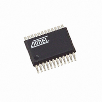
T89C5121-ICUIL Atmel, T89C5121-ICUIL Datasheet - Page 86

T89C5121-ICUIL
Manufacturer Part Number
T89C5121-ICUIL
Description
IC 8051 MCU W/SMART CARD 24SSOP
Manufacturer
Atmel
Series
89Cr
Datasheet
1.89C5121-SK1.pdf
(115 pages)
Specifications of T89C5121-ICUIL
Core Processor
8051
Core Size
8-Bit
Speed
16MHz
Connectivity
SmartCard, UART/USART
Peripherals
LED, POR, WDT
Number Of I /o
14
Program Memory Size
16KB (16K x 8)
Program Memory Type
Flash RAM
Eeprom Size
16K x 8
Ram Size
256 x 8
Voltage - Supply (vcc/vdd)
2.85 V ~ 5.4 V
Oscillator Type
Internal
Operating Temperature
-40°C ~ 85°C
Package / Case
24-SSOP
Lead Free Status / RoHS Status
Contains lead / RoHS non-compliant
Data Converters
-
Other names
Q1468934
T89C5121-ICSIL
T89C5121-ICSIL
T89C5121-ICSIL
T89C5121-ICSIL
UART Timings
Mode Selection
Baud Rate Generator
Timer 1
Figure 36. Timer 1 Baud Rate Generator Block Diagram
Internal Baud Rate Generator
86
INT1
CLOCK
PER
T1
A/T8xC5121
GATE1
TMOD.7
6
TMOD.6
C/T1#
TCON.6
TR1
0
1
The following description will be included in L version:
SM0 and SM1 bits in SCON register (see Table 67) are used to select a mode among
the single synchronous and the three asynchronous modes according to Table 64.
Table 64. Serial I/O Port Mode Selection
Depending on the mode and the source selection, the baud rate can be generated from
either the Timer 1 or the Internal Baud Rate Generator. The Timer 1 can be used in
Modes 1 and 3 while the Internal Baud Rate Generator can be used in Modes 0, 1 and
3.
The addition of the Internal Baud Rate Generator allows freeing of the Timer 1 for other
purposes in the application. It is highly recommended to use the Internal Baud Rate
Generator as it allows higher and more accurate baud rates than with Timer 1.
Baud rate formulas depend on the modes selected and are given in the following mode
sections.
When using the Timer 1, the Baud Rate is derived from the overflow of the timer. As
shown in Figure 36 the Timer 1 is used in its 8-bit auto-reload mode (detailed in
Section “Timer 0/Counter Operations”, page 73). SMOD1 bit in PCON register allows
doubling of the generated baud rate.
When using the Internal Baud Rate Generator, the Baud Rate is derived from the over-
flow of the timer. As shown in Figure 37, the Internal Baud Rate Generator is an 8-bit
auto-reload timer feed by the peripheral clock or by the peripheral clock divided by 6
depending on the SPD bit in BDRCON register (see Table 68). The Internal Baud Rate
Generator is enabled by setting BBR bit in BDRCON register. SMOD1 bit in PCON reg-
ister allows doubling of the generated baud rate.
SM0
0
0
1
1
SM1
0
1
0
1
Mode
(8 bits)
(8 bits)
TH1
0
1
2
3
TL1
Description
Synchronous Shift Register
8-bit UART
9-bit UART
9-bit UART
Overflow
2
SMOD1
PCON.7
0
1
CLOCK
T1
Baud Rate
Fixed / Variable
Variable
Fixed
Variable
To Serial Port
4164G–SCR–07/06


