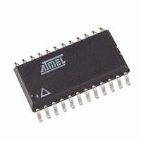
T89C51CC02CA-TDSIM Atmel, T89C51CC02CA-TDSIM Datasheet - Page 9

T89C51CC02CA-TDSIM
Manufacturer Part Number
T89C51CC02CA-TDSIM
Description
IC 8051 MCU FLASH 16K 24SOIC
Manufacturer
Atmel
Series
AT89C CANr
Datasheets
1.T89C51CC02CA-TDSIM.pdf
(159 pages)
2.T89C51CC02CA-TDSIM.pdf
(33 pages)
3.T89C51CC02CA-TDSIM.pdf
(29 pages)
4.T89C51CC02CA-TDSIM.pdf
(148 pages)
Specifications of T89C51CC02CA-TDSIM
Core Processor
8051
Core Size
8-Bit
Speed
40MHz
Connectivity
CAN, UART/USART
Peripherals
POR, PWM, WDT
Number Of I /o
20
Program Memory Size
16KB (16K x 8)
Program Memory Type
FLASH
Eeprom Size
2K x 8
Ram Size
512 x 8
Voltage - Supply (vcc/vdd)
3 V ~ 5.5 V
Data Converters
A/D 8x10b
Oscillator Type
External
Operating Temperature
-40°C ~ 85°C
Package / Case
24-SOIC (7.5mm Width)
For Use With
AT89STK-06 - KIT DEMOBOARD 8051 MCU W/CAN
Lead Free Status / RoHS Status
Contains lead / RoHS non-compliant
Other names
T89C51CC02CATDSIM
CAN Autobaud
CAN Autobaud
Limitation
Protocol
Generic CAN Frame
Description
Command Description
4208D–CAN–03/08
The following table shows the autobaud performance for a point-to-point connection in X1 mode.
Note:
The CAN Autobaud implemented in the bootloader is efficient only in point-to-point connection.
Because in a point-to-point connection, the transmit CAN message is repeated until a hardware
acknowledge is done by the receiver.
The bootloader can acknowledge an incoming CAN frame only if a configuration is found.
This functionality is not guaranteed on a network with several CAN nodes.
•
•
•
The CAN Protocol manages directly using hardware a checksum and an acknowledge.
Note:
This protocol allows to:
•
•
•
•
•
•
•
Overview of the protocol is detailed in Appendix-A.
Several CAN message identifiers are defined to manage this protocol.
Identifier: Identifies the frame (or message). Only the standard mode (11-bit) is used.
Control: Contains the DLC information (number of data in Data field) 4-bit.
Data: The data field consists of zero to eight bytes. The interpretation within the frame
depends on the Identifier field.
Initialize the communication
Program the Flash or EEPROM Data
Read the Flash or EEPROM Data
Program Configuration Information
Read Configuration and Manufacturer Information
Erase the Flash
Start the application
Identifier
ID_SELECT_NODE
100K
125K
250K
500K
20K
1M
1. ‘–’ Indicates impossible configuration.
To describe the ISP CAN Protocol, we use Symbolic name for Identifier, but default values are
given.
Identifier
8 MHz
11-bit
–
11.059
MHz
–
12 MHz 16 MHz 20 MHz
Command Effect
Open/Close a communication with a node
–
T89C51CC02 CAN Bootloader
–
Control
1 byte
22.1184
MHz
24 MHz 25 MHz 32 MHz 40 MHz
8 bytes max
Data
–
–
[CRIS]0h
Value
9


