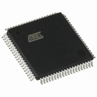
AT89C5132-ROTUL Atmel, AT89C5132-ROTUL Datasheet - Page 14

AT89C5132-ROTUL
Manufacturer Part Number
AT89C5132-ROTUL
Description
IC 8051 MCU FLASH 64K USB 80TQFP
Manufacturer
Atmel
Series
AT89C513xr
Specifications of AT89C5132-ROTUL
Core Processor
C52X2
Core Size
8-Bit
Speed
20MHz
Connectivity
IDE/ATAPI, I²C, MMC, PCM, SPI, UART/USART, USB
Peripherals
I²S, POR, WDT
Number Of I /o
44
Program Memory Size
64KB (64K x 8)
Program Memory Type
FLASH
Eeprom Size
4K x 8
Ram Size
2.25K x 8
Voltage - Supply (vcc/vdd)
2.7 V ~ 3.3 V
Data Converters
A/D 2x10b
Oscillator Type
Internal
Operating Temperature
-40°C ~ 85°C
Package / Case
80-TQFP, 80-VQFP
Cpu Family
89C
Device Core
8051
Device Core Size
8b
Frequency (max)
40MHz
Interface Type
IDE/SPI/UART/USB
Total Internal Ram Size
2.25KB
# I/os (max)
44
Number Of Timers - General Purpose
2
Operating Supply Voltage (typ)
3V
Operating Supply Voltage (max)
3.3V
Operating Supply Voltage (min)
2.7V
On-chip Adc
2-chx10-bit
Instruction Set Architecture
CISC
Operating Temp Range
-40C to 85C
Operating Temperature Classification
Industrial
Mounting
Surface Mount
Pin Count
80
Package Type
TQFP
Package
80TQFP
Family Name
89C
Maximum Speed
40 MHz
Operating Supply Voltage
3 V
Data Bus Width
8 Bit
Number Of Programmable I/os
44
Number Of Timers
2
Maximum Clock Frequency
20 MHz
Data Ram Size
2304 B
Mounting Style
SMD/SMT
A/d Bit Size
10 bit
A/d Channels Available
2
Height
1.45 mm
Length
14.1 mm
Maximum Operating Temperature
+ 85 C
Minimum Operating Temperature
- 40 C
Supply Voltage (max)
3.3 V
Supply Voltage (min)
2.7 V
Width
14.1 mm
For Use With
AT89OCD-01 - USB EMULATOR FOR AT8XC51 MCU
Lead Free Status / RoHS Status
Lead free / RoHS Compliant
Available stocks
Company
Part Number
Manufacturer
Quantity
Price
6.3.2
6.4
14
Registers
AT89C5132
PLL Programming
Figure 6-4.
Figure 6-5.
The PLL is programmed using the flow shown in Figure 6-6. As soon as clock generation is
enabled, the user must wait until the lock indicator is set to ensure the clock output is stable. The
PLL clock frequency will depend on the audio interface clock frequencies.
Figure 6-6.
Table 1. CKCON Register
CLOCK
OSC
PLL Block Diagram and Symbol
PLL Filter Connection
PLL Programming Flow
PLLclk
N divider
N6:0
=
PFILT
OSCclk
---------------------------------------------- -
N
PLLCON.1
PLLCON.0
PLOCK
PLLEN
+
×
PFLD
Configure Dividers
R9:0 = xxxxxxxxxxb
1
(
Programming
R
N6:0 = xxxxxxb
PLOCK = 1?
PLL Locked?
PLLRES = 0
Enable PLL
PLLEN = 1
+
V
1
PLL
SS
)
R
Down
C1
Up
V
R divider
SS
R9:0
PFILT
C2
CHP
Vref
VCO
PLL Clock Symbol
CLOCK
PLL
4173E–USB–09/07
PLL
Clock


