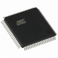
AT89C5132-ROTUL Atmel, AT89C5132-ROTUL Datasheet - Page 19

AT89C5132-ROTUL
Manufacturer Part Number
AT89C5132-ROTUL
Description
IC 8051 MCU FLASH 64K USB 80TQFP
Manufacturer
Atmel
Series
AT89C513xr
Specifications of AT89C5132-ROTUL
Core Processor
C52X2
Core Size
8-Bit
Speed
20MHz
Connectivity
IDE/ATAPI, I²C, MMC, PCM, SPI, UART/USART, USB
Peripherals
I²S, POR, WDT
Number Of I /o
44
Program Memory Size
64KB (64K x 8)
Program Memory Type
FLASH
Eeprom Size
4K x 8
Ram Size
2.25K x 8
Voltage - Supply (vcc/vdd)
2.7 V ~ 3.3 V
Data Converters
A/D 2x10b
Oscillator Type
Internal
Operating Temperature
-40°C ~ 85°C
Package / Case
80-TQFP, 80-VQFP
Cpu Family
89C
Device Core
8051
Device Core Size
8b
Frequency (max)
40MHz
Interface Type
IDE/SPI/UART/USB
Total Internal Ram Size
2.25KB
# I/os (max)
44
Number Of Timers - General Purpose
2
Operating Supply Voltage (typ)
3V
Operating Supply Voltage (max)
3.3V
Operating Supply Voltage (min)
2.7V
On-chip Adc
2-chx10-bit
Instruction Set Architecture
CISC
Operating Temp Range
-40C to 85C
Operating Temperature Classification
Industrial
Mounting
Surface Mount
Pin Count
80
Package Type
TQFP
Package
80TQFP
Family Name
89C
Maximum Speed
40 MHz
Operating Supply Voltage
3 V
Data Bus Width
8 Bit
Number Of Programmable I/os
44
Number Of Timers
2
Maximum Clock Frequency
20 MHz
Data Ram Size
2304 B
Mounting Style
SMD/SMT
A/d Bit Size
10 bit
A/d Channels Available
2
Height
1.45 mm
Length
14.1 mm
Maximum Operating Temperature
+ 85 C
Minimum Operating Temperature
- 40 C
Supply Voltage (max)
3.3 V
Supply Voltage (min)
2.7 V
Width
14.1 mm
For Use With
AT89OCD-01 - USB EMULATOR FOR AT8XC51 MCU
Lead Free Status / RoHS Status
Lead free / RoHS Compliant
Available stocks
Company
Part Number
Manufacturer
Quantity
Price
7.3
7.3.1
7.3.2
7.3.3
Figure 7-3.
4173E–USB–09/07
Boot Memory Execution
Software Boot Mapping
Hardware Condition Boot Mapping
Programmed Condition Boot Mapping
Hardware Boot Process Algorithm
As internal C51 code space is limited to 64K Bytes, some mechanisms are implemented to allow
boot memory to be mapped in the code space for execution at addresses from F000h to FFFFh.
The boot memory is enabled by setting the ENBOOT bit in AUXR1 (see
ways to set this bit are detailed in the following sections.
The software way to set ENBOOT consists in writing to AUXR1 from the user’s software. This
enables bootloader or API routines execution.
The hardware condition is based on the ISP pin. When driving this pin to low level, the chip reset
sets ENBOOT and forces the reset vector to F000h instead of 0000h in order to execute the
bootloader software.
As shown in Figure 7-3, the hardware condition always allows in-system recovery when user’s
memory has been corrupted.
The programmed condition is based on the Bootloader Jump Bit (BLJB) in HSB. As shown in
Figure 7-3, when this bit is programmed (by hardware or software programming mode), the chip
resets ENBOOT and forces the reset vector to F000h instead of 0000h, in order to execute the
bootloader software.
The software process (bootloader) is detailed in the AT89C5132 Bootloader datasheet.
Application
Standard Init
ENBOOT = 0
FCON = F0h
PC = 0000h
User’s
Prog Cond Init
Boot Loader
ENBOOT = 1
Hard Cond?
Prog Cond?
FCON = F0h
PC = F000h
BLJB = P?
Atmel’s
RESET
ISP = L?
Hard Cond Init
ENBOOT = 1
FCON = 00h
PC = F000h
AT89C5132
Table
6). The three
19


