SAK-C167CS-LM CA+ Infineon Technologies, SAK-C167CS-LM CA+ Datasheet - Page 16
SAK-C167CS-LM CA+
Manufacturer Part Number
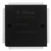
SAK-C167CS-LM CA+
Description
IC MCU 16BIT 25MHZ MQFP-144
Manufacturer
Infineon Technologies
Series
C16xxr
Datasheet
1.SAK-C167CS-LM_CA.pdf
(81 pages)
Specifications of SAK-C167CS-LM CA+
Core Processor
C166
Core Size
16-Bit
Speed
25MHz
Connectivity
CAN, EBI/EMI, SPI, SSC, UART/USART
Peripherals
POR, PWM, WDT
Number Of I /o
111
Program Memory Type
ROMless
Ram Size
11K x 8
Voltage - Supply (vcc/vdd)
4.5 V ~ 5.5 V
Data Converters
A/D 24x10b
Oscillator Type
External
Operating Temperature
-40°C ~ 125°C
Package / Case
144- BSQFP
Packages
PG-MQFP-144
Max Clock Frequency
25.0 MHz
Sram (incl. Cache)
11.0 KByte
Can Nodes
2
A / D Input Lines (incl. Fadc)
24
Program Memory
0.0 KByte
Lead Free Status / RoHS Status
Lead free / RoHS Compliant
Eeprom Size
-
Program Memory Size
-
Other names
K167CSLMCAZNP
K167CSLMCAZXP
K167CSLMCAZXT
SAK-C167CS-LM CA+
SAK-C167CS-LMCAIN
SAKC167CSLMCAT
SP000103492
K167CSLMCAZXP
K167CSLMCAZXT
SAK-C167CS-LM CA+
SAK-C167CS-LMCAIN
SAKC167CSLMCAT
SP000103492


Table 2
Symbol Pin
RSTIN
RST
OUT
NMI
V
V
Data Sheet
AREF
AGND
Num.
140
141
142
37
38
Pin Definitions and Functions (cont’d)
Input
Outp.
I/O
O
I
–
–
Function
Reset Input with Schmitt-Trigger characteristics. A low level
at this pin while the oscillator is running resets the C167CS.
An internal pullup resistor permits power-on reset using only
a capacitor connected to
A spike filter suppresses input pulses <10 ns. Input pulses
>100 ns safely pass the filter. The minimum duration for a
safe recognition should be 100 ns + 2 CPU clock cycles.
In bidirectional reset mode (enabled by setting bit BDRSTEN
in register SYSCON) the RSTIN line is internally pulled low
for the duration of the internal reset sequence upon any reset
(HW, SW, WDT). See note below this table.
Note: To let the reset configuration of PORT0 settle and to
Internal Reset Indication Output. This pin is set to a low level
when the part is executing either a hardware-, a software- or
a watchdog timer reset. RSTOUT remains low until the EINIT
(end of initialization) instruction is executed.
Non-Maskable Interrupt Input. A high to low transition at this
pin causes the CPU to vector to the NMI trap routine. When
the PWRDN (power down) instruction is executed, the NMI
pin must be low in order to force the C167CS to go into power
down mode. If NMI is high, when PWRDN is executed, the
part will continue to run in normal mode.
If not used, pin NMI should be pulled high externally.
Reference voltage for the A/D converter.
Reference ground for the A/D converter.
let the PLL lock a reset duration of ca. 1 ms is
recommended.
12
V
SS
.
C167CS-4R
V2.2, 2001-08
C167CS-L
Related parts for SAK-C167CS-LM CA+
Image
Part Number
Description
Manufacturer
Datasheet
Request
R

Part Number:
Description:
EOL: REPL: SAK-C167CS-L40M CA+; LTB(d/m/y):17/04/2007; LTS:17/10/2007
Manufacturer:
Infineon Technologies AG
Datasheet:
Part Number:
Description:
16-Bit Single-Chip Microcontroller
Manufacturer:
Infineon Technologies AG
Datasheet:
Part Number:
Description:
16 Bit Single-Chip Microcontroller
Manufacturer:
Infineon Technologies AG
Datasheet:

Part Number:
Description:
Manufacturer:
Infineon Technologies
Datasheet:
Part Number:
Description:
Manufacturer:
Infineon Technologies
Datasheet:
Part Number:
Description:
QFP 144/16BIT ROM/ROMLESS
Manufacturer:
Infineon Technologies AG

Part Number:
Description:
IC MCU 16BIT 40MHZ MQFP-144
Manufacturer:
Infineon Technologies
Datasheet:
Part Number:
Description:
IC MCU 16BIT 33MHZ MQFP-144
Manufacturer:
Infineon Technologies
Datasheet:
Part Number:
Description:
Manufacturer:
Infineon Technologies
Datasheet:
Part Number:
Description:
16-Bit Single-Chip Microcontroller
Manufacturer:
Infineon Technologies AG
Datasheet:
Part Number:
Description:
Manufacturer:
Infineon Technologies AG
Datasheet:
Part Number:
Description:
Manufacturer:
Infineon Technologies AG
Datasheet:
Part Number:
Description:
Manufacturer:
Infineon Technologies AG
Datasheet:
Part Number:
Description:
Manufacturer:
Infineon Technologies AG
Datasheet: