C8051F901-GU Silicon Laboratories Inc, C8051F901-GU Datasheet - Page 185
C8051F901-GU
Manufacturer Part Number
C8051F901-GU
Description
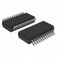
IC MCU 8BIT 8KB FLASH 24QSOP
Manufacturer
Silicon Laboratories Inc
Series
C8051F9xxr
Specifications of C8051F901-GU
Program Memory Type
FLASH
Program Memory Size
8KB (8K x 8)
Package / Case
24-QSOP
Core Processor
8051
Core Size
8-Bit
Speed
25MHz
Connectivity
SMBus (2-Wire/I²C), SPI, UART/USART
Peripherals
Brown-out Detect/Reset, POR, PWM, Temp Sensor, WDT
Number Of I /o
16
Ram Size
768 x 8
Voltage - Supply (vcc/vdd)
0.9 V ~ 3.6 V
Data Converters
A/D 15x10b
Oscillator Type
Internal
Operating Temperature
-40°C ~ 85°C
Processor Series
C8051F9x
Core
8051
Data Ram Size
768 B
Interface Type
UART
Maximum Clock Frequency
25 MHz
Number Of Timers
4
Operating Supply Voltage
0.9 V to 3.6 V
Maximum Operating Temperature
+ 85 C
Mounting Style
SMD/SMT
3rd Party Development Tools
PK51, CA51, A51, ULINK2
Development Tools By Supplier
C8051F912DK
Minimum Operating Temperature
- 40 C
On-chip Adc
10 bit
Package
24QSOP
Device Core
8051
Family Name
C8051F90x
Maximum Speed
25 MHz
Data Bus Width
8 Bit
Number Of Programmable I/os
16
Lead Free Status / RoHS Status
Lead free / RoHS Compliant
Eeprom Size
-
Lead Free Status / Rohs Status
Lead free / RoHS Compliant
Other names
336-1847-5
Available stocks
Company
Part Number
Manufacturer
Quantity
Price
Company:

Part Number:
C8051F901-GU
Manufacturer:
Silicon Laboratories Inc
Quantity:
135


19.4. Special Function Registers for Selecting and Configuring the System Clock
The clocking sources on C8051F91x-C8051F90x devices are enabled and configured using the OSCICN,
OSCICL, OSCXCN and the SmaRTClock internal registers. See Section “20. SmaRTClock (Real Time
Clock)” on page 188 for SmaRTClock register descriptions. The system clock source for the MCU can be
selected using the CLKSEL register. To minimize active mode current, the oneshot timer which sets Flash
read time should by bypassed when the system clock is greater than 10 MHz. See the FLSCL register
description for details.
The clock selected as the system clock can be divided by 1, 2, 4, 8, 16, 32, 64, or 128. When switching
between two clock divide values, the transition may take up to 128 cycles of the undivided clock source.
The CLKRDY flag can be polled to determine when the new clock divide value has been applied. The clock
divider must be set to "divide by 1" when entering Suspend or Sleep Mode.
The system clock source may also be switched on-the-fly. The switchover takes effect after one clock
period of the slower oscillator.
SFR Definition 19.1. CLKSEL: Clock Select
SFR Page = All Pages; SFR Address = 0xA9
Name
Reset
Type
6:4
2:0
Bit
Bit
7
3
CLKRDY
CLKSEL[2:0] System Clock Select.
CLKDIV[2:0]
CLKRDY
Unused
R
Name
7
0
R/W
System Clock Divider Clock Ready Flag.
0: The selected clock divide setting has not been applied to the system clock.
1: The selected clock divide setting has been applied to the system clock.
System Clock Divider Bits.
Selects the clock division to be applied to the undivided system clock source.
000: System clock is divided by 1.
001: System clock is divided by 2.
010: System clock is divided by 4.
011: System clock is divided by 8.
100: System clock is divided by 16.
101: System clock is divided by 32.
110: System clock is divided by 64.
111: System clock is divided by 128.
Unused.
Read = 0b. Must Write 0b.
Selects the oscillator to be used as the undivided system clock source.
000: Precision Internal Oscillator.
001: External Oscillator.
011: SmaRTClock Oscillator.
100: Low Power Oscillator.
All other values reserved.
6
0
CLKDIV[2:0]
R/W
5
1
R/W
Rev. 1.0
4
1
C8051F91x-C8051F90x
R/W
Function
3
0
R/W
2
1
CLKSEL[2:0]
R/W
1
0
R/W
0
0
185
Related parts for C8051F901-GU
Image
Part Number
Description
Manufacturer
Datasheet
Request
R

Part Number:
Description:
SMD/C°/SINGLE-ENDED OUTPUT SILICON OSCILLATOR
Manufacturer:
Silicon Laboratories Inc
Part Number:
Description:
Manufacturer:
Silicon Laboratories Inc
Datasheet:
Part Number:
Description:
N/A N/A/SI4010 AES KEYFOB DEMO WITH LCD RX
Manufacturer:
Silicon Laboratories Inc
Datasheet:
Part Number:
Description:
N/A N/A/SI4010 SIMPLIFIED KEY FOB DEMO WITH LED RX
Manufacturer:
Silicon Laboratories Inc
Datasheet:
Part Number:
Description:
N/A/-40 TO 85 OC/EZLINK MODULE; F930/4432 HIGH BAND (REV E/B1)
Manufacturer:
Silicon Laboratories Inc
Part Number:
Description:
EZLink Module; F930/4432 Low Band (rev e/B1)
Manufacturer:
Silicon Laboratories Inc
Part Number:
Description:
I°/4460 10 DBM RADIO TEST CARD 434 MHZ
Manufacturer:
Silicon Laboratories Inc
Part Number:
Description:
I°/4461 14 DBM RADIO TEST CARD 868 MHZ
Manufacturer:
Silicon Laboratories Inc
Part Number:
Description:
I°/4463 20 DBM RFSWITCH RADIO TEST CARD 460 MHZ
Manufacturer:
Silicon Laboratories Inc
Part Number:
Description:
I°/4463 20 DBM RADIO TEST CARD 868 MHZ
Manufacturer:
Silicon Laboratories Inc
Part Number:
Description:
I°/4463 27 DBM RADIO TEST CARD 868 MHZ
Manufacturer:
Silicon Laboratories Inc
Part Number:
Description:
I°/4463 SKYWORKS 30 DBM RADIO TEST CARD 915 MHZ
Manufacturer:
Silicon Laboratories Inc
Part Number:
Description:
N/A N/A/-40 TO 85 OC/4463 RFMD 30 DBM RADIO TEST CARD 915 MHZ
Manufacturer:
Silicon Laboratories Inc
Part Number:
Description:
I°/4463 20 DBM RADIO TEST CARD 169 MHZ
Manufacturer:
Silicon Laboratories Inc