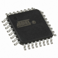
ATTINY28L-4AU Atmel, ATTINY28L-4AU Datasheet - Page 24

ATTINY28L-4AU
Manufacturer Part Number
ATTINY28L-4AU
Description
IC MCU AVR 2K FLASH 4MHZ 32-TQFP
Manufacturer
Atmel
Series
AVR® ATtinyr
Specifications of ATTINY28L-4AU
Core Processor
AVR
Core Size
8-Bit
Speed
4MHz
Peripherals
POR, WDT
Number Of I /o
11
Program Memory Size
2KB (1K x 16)
Program Memory Type
FLASH
Voltage - Supply (vcc/vdd)
2.7 V ~ 5.5 V
Oscillator Type
Internal
Operating Temperature
-40°C ~ 85°C
Package / Case
32-TQFP, 32-VQFP
Processor Series
ATTINY2x
Core
AVR8
Data Bus Width
8 bit
Data Ram Size
32 B
Maximum Clock Frequency
4 MHz
Number Of Programmable I/os
11
Number Of Timers
1
Maximum Operating Temperature
+ 85 C
Mounting Style
SMD/SMT
3rd Party Development Tools
EWAVR, EWAVR-BL
Development Tools By Supplier
ATAVRDRAGON, ATSTK500, ATSTK600, ATAVRISP2, ATAVRONEKIT
Minimum Operating Temperature
- 40 C
On-chip Adc
8 bit
Package
32TQFP
Device Core
AVR
Family Name
ATtiny
Maximum Speed
4 MHz
Ram Size
32 Byte
Operating Supply Voltage
3.3|5 V
For Use With
ATSTK600-DIP40 - STK600 SOCKET/ADAPTER 40-PDIPATSTK500 - PROGRAMMER AVR STARTER KIT
Lead Free Status / RoHS Status
Lead free / RoHS Compliant
Eeprom Size
-
Ram Size
-
Data Converters
-
Connectivity
-
Lead Free Status / Rohs Status
Details
Available stocks
Company
Part Number
Manufacturer
Quantity
Price
24
ATtiny28L/V
enable bit, INT0 in GIMSK is set (one), the MCU will jump to the interrupt vector. The
flag is cleared when the interrupt routine is executed. Alternatively, the flag can be
cleared by writing a logical “1” to it. This flag is always cleared when INT0 is configured
as level interrupt.
• Bit 5 – Res: Reserved Bit
This bit is a reserved bit in the ATtiny28 and always reads as zero.
• Bit 4 – TOV0: Timer/Counter0 Overflow Flag
The bit TOV0 is set (one) when an overflow occurs in Timer/Counter0. TOV0 is cleared
by hardware when executing the corresponding interrupt handling vector. TOV0 is
cleared by writing a logical “1” to the flag. When the SREG I-bit, TOIE0 in ICR and TOV0
are set (one), the Timer/Counter0 Overflow interrupt is executed.
• Bit 3..0 - Res: Reserved Bits
These bits are reserved bits in the ATtiny28 and always read as zero.
Note:
1. One should not try to use the SBI (Set Bit in I/O Register) instruction to clear individ-
ual flags in the Register. This will result in clearing all the flags in the register,
because the register is first read, then modified and finally written, thus writing ones
to all set flags. Using the CBI (Clear Bit in I/O Register) instruction on IFR will result in
clearing all bits apart from the specified bit.
1062F–AVR–07/06


