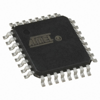
ATTINY28L-4AU Atmel, ATTINY28L-4AU Datasheet - Page 28

ATTINY28L-4AU
Manufacturer Part Number
ATTINY28L-4AU
Description
IC MCU AVR 2K FLASH 4MHZ 32-TQFP
Manufacturer
Atmel
Series
AVR® ATtinyr
Specifications of ATTINY28L-4AU
Core Processor
AVR
Core Size
8-Bit
Speed
4MHz
Peripherals
POR, WDT
Number Of I /o
11
Program Memory Size
2KB (1K x 16)
Program Memory Type
FLASH
Voltage - Supply (vcc/vdd)
2.7 V ~ 5.5 V
Oscillator Type
Internal
Operating Temperature
-40°C ~ 85°C
Package / Case
32-TQFP, 32-VQFP
Processor Series
ATTINY2x
Core
AVR8
Data Bus Width
8 bit
Data Ram Size
32 B
Maximum Clock Frequency
4 MHz
Number Of Programmable I/os
11
Number Of Timers
1
Maximum Operating Temperature
+ 85 C
Mounting Style
SMD/SMT
3rd Party Development Tools
EWAVR, EWAVR-BL
Development Tools By Supplier
ATAVRDRAGON, ATSTK500, ATSTK600, ATAVRISP2, ATAVRONEKIT
Minimum Operating Temperature
- 40 C
On-chip Adc
8 bit
Package
32TQFP
Device Core
AVR
Family Name
ATtiny
Maximum Speed
4 MHz
Ram Size
32 Byte
Operating Supply Voltage
3.3|5 V
For Use With
ATSTK600-DIP40 - STK600 SOCKET/ADAPTER 40-PDIPATSTK500 - PROGRAMMER AVR STARTER KIT
Lead Free Status / RoHS Status
Lead free / RoHS Compliant
Eeprom Size
-
Ram Size
-
Data Converters
-
Connectivity
-
Lead Free Status / Rohs Status
Details
Available stocks
Company
Part Number
Manufacturer
Quantity
Price
Port B Schematics
28
ATtiny28L/V
• AIN1 – Port B, Bit 1
AIN1, Analog Comparator Negative input. When the on-chip analog comparator is
enabled, this pin also serves as the negative input of the comparator. If the analog com-
parator is enabled, the pull-up resistors on PB1 and PB0 are disabled and these pins will
not give low-level interrupts.
• AIN0 – Port B, Bit 0
AIN0, Analog Comparator Positive input. When the on-chip analog comparator is
enabled, this pin also serves as the positive input of the comparator. If the analog com-
parator is enabled, the pull-up resistors on PB1 and PB0 are disabled and these pins will
not give low-level interrupts.
Note that all port pins are synchronized. The synchronization latches are, however, not
shown in the figures.
Figure 23. Port B Schematic Diagram (Pins PB0 and PB1)
PBn
RP: READ PORTB PIN
n : 0, 1
MOS
PULL-
UP
PWRDN
TO LOW-LEVEL DETECTOR
TO COMPARATOR
RP
PULL-UP PORT B
COMPARATOR DISABLE
AINn
1062F–AVR–07/06


