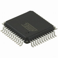
AT32UC3L064-AUR Atmel, AT32UC3L064-AUR Datasheet - Page 39

AT32UC3L064-AUR
Manufacturer Part Number
AT32UC3L064-AUR
Description
IC MCU AVR32 64K FLASH 48TQFP
Manufacturer
Atmel
Series
AVR®32 UC3r
Datasheet
1.AT32UC3L016-ZAUR.pdf
(71 pages)
Specifications of AT32UC3L064-AUR
Package / Case
48-TQFP, 48-VQFP
Voltage - Supply (vcc/vdd)
1.62 V ~ 1.98 V
Operating Temperature
-40°C ~ 85°C
Speed
50MHz
Number Of I /o
36
Core Processor
AVR
Program Memory Type
FLASH
Ram Size
16K x 8
Program Memory Size
64KB (64K x 8)
Data Converters
A/D 9x10b
Oscillator Type
Internal
Peripherals
Brown-out Detect/Reset, DMA, PWM, WDT
Connectivity
I²C, SPI, UART/USART
Core Size
32-Bit
Lead Free Status / RoHS Status
Lead free / RoHS Compliant
Eeprom Size
-
Available stocks
Company
Part Number
Manufacturer
Quantity
Price
Company:
Part Number:
AT32UC3L064-AUR
Manufacturer:
ATMEL
Quantity:
101
6. Boot Sequence
6.1
6.2
6.3
32099AS–AVR32–06/09
Starting of Clocks
Fetching of Initial Instructions
RC32K Clock Output at Startup
This chapter summarizes the boot sequence of the AT32UC3L. The behavior after power-up is
controlled by the Power Manager. For specific details, refer to the Power Manager chapter.
After power-up, the device will be held in a reset state by the Power-On Reset circuitry for a
short time to allow the power to stabilize throughout the device. After reset, the device will use
the System RC Oscillator (RCSYS) as clock source. Please refer to
the frequency for this oscillotor.
On system start-up, the DFLL is disabled. All clocks to all modules are running. No clocks have
a divided frequency; all parts of the system receive a clock with the same frequency as the Sys-
tem RC Oscillator.
After reset has been released, the AVR32 UC CPU starts fetching instructions from the reset
address, which is 0x80000000. This address points to the first address in the internal Flash.
The code read from the internal Flash is free to configure the system to use for example the
DFLL, to divide the frequency of the clock routed to some of the peripherals, and to gate the
clocks to unused peripherals.
After power-up, the clock generated by the 32kHz RC oscillator (RC32K) will be output on I/O
line PA20, even when the device is still reset by the Power-On Reset Circuitry.
This clock can be used by the system to start other devices or to clock a switching regulator to
rise the power supply voltage up to an acceptable value.
The clock will be available on I/O line PA20 until one of the following conditions are true:
• PA20 is configured to use a GPIO function other than F (SCIF-RC32OUT)
• PA20 is configured as a General Purpose Input/Output (GPIO)
• The bit FRC32 in the Power Manager PPCR register is cleared (see Power Manager chapter)
The maximum amplitude of the clock signal will be defined by VDDIN.
Table 7-20 on page 48
AT32UC3L
for
39


