P87C51RC2BBD,157 NXP Semiconductors, P87C51RC2BBD,157 Datasheet - Page 36
P87C51RC2BBD,157
Manufacturer Part Number
P87C51RC2BBD,157
Description
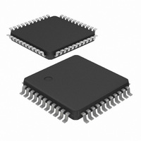
IC 80C51 MCU 512 RAM 44LQFP
Manufacturer
NXP Semiconductors
Series
87Cr
Datasheet
1.P87C51RC2FA512.pdf
(67 pages)
Specifications of P87C51RC2BBD,157
Program Memory Type
OTP
Program Memory Size
32KB (32K x 8)
Package / Case
44-LQFP
Core Processor
8051
Core Size
8-Bit
Speed
33MHz
Connectivity
EBI/EMI, UART/USART
Peripherals
POR, PWM, WDT
Number Of I /o
32
Ram Size
512 x 8
Voltage - Supply (vcc/vdd)
2.7 V ~ 5.5 V
Oscillator Type
Internal
Operating Temperature
0°C ~ 70°C
Processor Series
P87C51
Core
80C51
Data Bus Width
8 bit
Data Ram Size
512 B
Interface Type
UART
Maximum Clock Frequency
16 MHz
Number Of Programmable I/os
32
Number Of Timers
4
Operating Supply Voltage
2.7 V to 5.5 V
Maximum Operating Temperature
+ 70 C
Mounting Style
SMD/SMT
3rd Party Development Tools
PK51, CA51, A51, ULINK2
Minimum Operating Temperature
0 C
Package
44LQFP
Device Core
80C51
Family Name
87C
Maximum Speed
33 MHz
Cpu Family
87C
Device Core Size
8b
Frequency (max)
33MHz
Total Internal Ram Size
512Byte
# I/os (max)
32
Number Of Timers - General Purpose
3
Operating Supply Voltage (typ)
3.3/5V
Operating Supply Voltage (max)
5.5V
Operating Supply Voltage (min)
2.7V
Instruction Set Architecture
CISC
Operating Temp Range
0C to 70C
Operating Temperature Classification
Commercial
Mounting
Surface Mount
Pin Count
44
Package Type
LQFP
Lead Free Status / RoHS Status
Lead free / RoHS Compliant
For Use With
OM10064 - EMULATOR 80C51 PDS51-MK2
Eeprom Size
-
Data Converters
-
Lead Free Status / Rohs Status
Compliant
Other names
935272152157
P87C51RC2BBD
P87C51RC2BBD
P87C51RC2BBD
P87C51RC2BBD
Available stocks
Company
Part Number
Manufacturer
Quantity
Price
Company:

Part Number:
P87C51RC2BBD,157
Manufacturer:
NXP Semiconductors
Quantity:
10 000


Philips Semiconductors
PCA Capture Mode
To use one of the PCA modules in the capture mode either one or
both of the CCAPM bits CAPN and CAPP for that module must be
set. The external CEX input for the module (on port 1) is sampled for
a transition. When a valid transition occurs the PCA hardware loads
the value of the PCA counter registers (CH and CL) into the
module’s capture registers (CCAPnL and CCAPnH). If the CCFn bit
for the module in the CCON SFR and the ECCFn bit in the CCAPMn
SFR are set then an interrupt will be generated. Refer to Figure 26.
16-bit Software Timer Mode
The PCA modules can be used as software timers by setting both
the ECOM and MAT bits in the modules CCAPMn register. The PCA
timer will be compared to the module’s capture registers and when a
match occurs an interrupt will occur if the CCFn (CCON SFR) and
the ECCFn (CCAPMn SFR) bits for the module are both set (see
Figure 27).
High Speed Output Mode
In this mode the CEX output (on port 1) associated with the PCA
module will toggle each time a match occurs between the PCA
2003 Jan 24
80C51 8-bit microcontroller family
with 512B/1KB RAM, low voltage (2.7 to 5.5 V), low power, high
speed (30/33 MHz)
NOTE:
*User software should not write 1s to reserved bits. These bits may be used in future 8051 family products to invoke new features In that case, the reset or inactive
value of the new bit will be 0, and its active value will be 1. The value read from a reserved bit is indeterminate.
CCAPMn Address
Symbol
–
ECOMn
CAPPn
CAPNn
MATn
TOGn
PWMn
ECCFn
X
X
X
X
X
X
X
X
–
ECOMn
X
X
X
0
1
1
1
1
Not Bit Addressable
Bit:
Function
Not implemented, reserved for future use*.
Enable Comparator. ECOMn = 1 enables the comparator function.
Capture Positive, CAPPn = 1 enables positive edge capture.
Capture Negative, CAPNn = 1 enables negative edge capture.
Match. When MATn = 1, a match of the PCA counter with this module’s compare/capture register causes the CCFn bit
in CCON to be set, flagging an interrupt.
Toggle. When TOGn = 1, a match of the PCA counter with this module’s compare/capture register causes the CEXn
pin to toggle.
Pulse Width Modulation Mode. PWMn = 1 enables the CEXn pin to be used as a pulse width modulated output.
Enable CCF interrupt. Enables compare/capture flag CCFn in the CCON register to generate an interrupt.
CAPPn
0
1
0
1
0
0
0
0
–
7
CCAPM0
CCAPM1
CCAPM2
CCAPM3
CCAPM4
CAPNn
ECOMn
Figure 24. CCAPMn: PCA Modules Compare/Capture Registers
0
0
1
1
0
0
0
0
6
0DAH
0DBH
0DCH
0DDH
0DEH
Figure 25. PCA Module Modes (CCAPMn Register)
8KB/16KB/32KB/64KB OTP
MATn
CAPPn
0
0
0
0
1
1
0
1
5
TOGn
CAPNn
X
0
0
0
0
0
1
0
4
PWMn
36
MATn
0
0
0
0
0
0
1
0
3
counter and the module’s capture registers. To activate this mode
the TOG, MAT, and ECOM bits in the module’s CCAPMn SFR must
be set (see Figure 28).
Pulse Width Modulator Mode
All of the PCA modules can be used as PWM outputs. Figure 29
shows the PWM function. The frequency of the output depends on
the source for the PCA timer. All of the modules will have the same
frequency of output because they all share the PCA timer. The duty
cycle of each module is independently variable using the module’s
capture register CCAPLn. When the value of the PCA CL SFR is
less than the value in the module’s CCAPLn SFR the output will be
low, when it is equal to or greater than the output will be high. When
CL overflows from FF to 00, CCAPLn is reloaded with the value in
CCAPHn. the allows updating the PWM without glitches. The PWM
and ECOM bits in the module’s CCAPMn register must be set to
enable the PWM mode.
ECCFn
TOGn
X
X
X
X
X
X
0
0
2
No operation
16-bit capture by a positive-edge trigger on CEXn
16-bit capture by a negative trigger on CEXn
16-bit capture by a transition on CEXn
16-bit Software Timer
16-bit High Speed Output
8-bit PWM
Watchdog Timer
P87C51RA2/RB2/RC2/RD2
PWMn
1
ECCFn
MODULE FUNCTION
0
Reset Value = X000 0000B
Product data
SU01320
Related parts for P87C51RC2BBD,157
Image
Part Number
Description
Manufacturer
Datasheet
Request
R

Part Number:
Description:
NXP Semiconductors designed the LPC2420/2460 microcontroller around a 16-bit/32-bitARM7TDMI-S CPU core with real-time debug interfaces that include both JTAG andembedded trace
Manufacturer:
NXP Semiconductors
Datasheet:

Part Number:
Description:
NXP Semiconductors designed the LPC2458 microcontroller around a 16-bit/32-bitARM7TDMI-S CPU core with real-time debug interfaces that include both JTAG andembedded trace
Manufacturer:
NXP Semiconductors
Datasheet:
Part Number:
Description:
NXP Semiconductors designed the LPC2468 microcontroller around a 16-bit/32-bitARM7TDMI-S CPU core with real-time debug interfaces that include both JTAG andembedded trace
Manufacturer:
NXP Semiconductors
Datasheet:
Part Number:
Description:
NXP Semiconductors designed the LPC2470 microcontroller, powered by theARM7TDMI-S core, to be a highly integrated microcontroller for a wide range ofapplications that require advanced communications and high quality graphic displays
Manufacturer:
NXP Semiconductors
Datasheet:
Part Number:
Description:
NXP Semiconductors designed the LPC2478 microcontroller, powered by theARM7TDMI-S core, to be a highly integrated microcontroller for a wide range ofapplications that require advanced communications and high quality graphic displays
Manufacturer:
NXP Semiconductors
Datasheet:
Part Number:
Description:
The Philips Semiconductors XA (eXtended Architecture) family of 16-bit single-chip microcontrollers is powerful enough to easily handle the requirements of high performance embedded applications, yet inexpensive enough to compete in the market for hi
Manufacturer:
NXP Semiconductors
Datasheet:
Part Number:
Description:
The XA-S3 device is a member of Philips Semiconductors? XA(eXtended Architecture) family of high performance 16-bitsingle-chip microcontrollers
Manufacturer:
NXP Semiconductors
Datasheet:

Part Number:
Description:
The NXP BlueStreak LH75401/LH75411 family consists of two low-cost 16/32-bit System-on-Chip (SoC) devices
Manufacturer:
NXP Semiconductors
Datasheet:
Part Number:
Description:
The NXP LPC3130/3131 combine an 180 MHz ARM926EJ-S CPU core, high-speed USB2
Manufacturer:
NXP Semiconductors
Datasheet:
Part Number:
Description:
The NXP LPC3141 combine a 270 MHz ARM926EJ-S CPU core, High-speed USB 2
Manufacturer:
NXP Semiconductors
Part Number:
Description:
The NXP LPC3143 combine a 270 MHz ARM926EJ-S CPU core, High-speed USB 2
Manufacturer:
NXP Semiconductors

Part Number:
Description:
The NXP LPC3152 combines an 180 MHz ARM926EJ-S CPU core, High-speed USB 2
Manufacturer:
NXP Semiconductors
Part Number:
Description:
The NXP LPC3154 combines an 180 MHz ARM926EJ-S CPU core, High-speed USB 2
Manufacturer:
NXP Semiconductors

Part Number:
Description:
Standard level N-channel enhancement mode Field-Effect Transistor (FET) in a plastic package using NXP High-Performance Automotive (HPA) TrenchMOS technology
Manufacturer:
NXP Semiconductors
Datasheet: