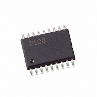
Z8PE003SZ010EG Zilog, Z8PE003SZ010EG Datasheet - Page 43

Z8PE003SZ010EG
Manufacturer Part Number
Z8PE003SZ010EG
Description
IC MICROCONTROLLER 1K 18-SOIC
Manufacturer
Zilog
Series
Z8® Plusr
Specifications of Z8PE003SZ010EG
Core Processor
Z8
Core Size
8-Bit
Speed
10MHz
Peripherals
Brown-out Detect/Reset, POR, PWM, WDT
Number Of I /o
14
Program Memory Size
1KB (1K x 8)
Program Memory Type
OTP
Ram Size
64 x 8
Voltage - Supply (vcc/vdd)
4.5 V ~ 5.5 V
Oscillator Type
Internal
Operating Temperature
-40°C ~ 105°C
Package / Case
18-SOIC (7.5mm Width)
Lead Free Status / RoHS Status
Lead free / RoHS Compliant
Eeprom Size
-
Data Converters
-
Connectivity
-
Other names
269-4294
Z8PE003SZ010EG
Z8PE003SZ010EG
ZiLOG
I/O PORT RESET CONDITIONS
Full Reset
Port A and Port B output value registers are not affected by
RESET
On
isters are cleared to all zeros, which defines all pins in both
ports as inputs.
On
as inputs, and the Port A and Port B input value registers
ANALOG COMPARATOR
The device includes one on-chip analog comparator. Pin
PB4
erence voltage is on pin
Comparator Description
The on-chip comparator can process an analog signal on
PB4
tion is enabled by programming the Port B special function
register bits 3 and 4.
COMPARATOR OPERATION
The comparator output reflects the relationship between the
analog input to the reference input. If the voltage on the an-
alog input is higher than the voltage on the reference input,
then the comparator output is at a High state. If the voltage
on the analog input is lower than the voltage on the reference
input, then the analog output is at a Low state.
Comparator Definitions
V
The usable voltage range for the positive input and
reference input is called the Comparator Input Common
Mode Voltage Range (
Note: The comparator is not guaranteed to work if the input is
V
The absolute value of the voltage between the positive input
and the reference input required to make the comparator
output voltage switch is the Comparator Input Offset Volt-
age (
DS007500-Z8X0399
ICR
OFFSET
RESET
RESET
with reference to the voltage on
features a comparator front end. The comparator ref-
V
OFFSET
outside of the
.
, the directional control registers redefine all pins
, the Port A and Port B directional control reg-
).
V
ICR
V
PB3
ICR
range.
).
.
PB3
. The analog func-
P R E L I M I N A R Y
overwrites the previously held data with the current sample
of the input pins.
On
are cleared to
tions.
Note: The
When the analog comparator function is enabled, bit 4 of
the input register is defined as holding the synchronized out-
put of the comparator, while bit 3 retains a synchronized
sample of the reference input.
If the interrupts for
special function is selected, the output of the comparator
generates interrupts.
I
For the CMOS voltage comparator input, the input offset current
(
HALT Mode
The analog comparator is functional during
the interrupts are enabled, an interrupt generated by the
comparator causes a return from
STOP Mode
The analog comparator is disabled during
comparator is powered down to prevent it from drawing any
current.
Low Voltage Protection.
ator checks that the
correct operation of the device. A reset is globally driven
if
tion).
The device functions normally at or above 3.0V under all
conditions, and is guaranteed to function normally at supply
voltages above the Low Voltage Protection trip point. Be-
low 3.0V, the device functions normally until the Low Volt-
IO
I
IO
V
) is the leakage current of the CMOS input gate.
RESET
CC
is below the specified voltage (Low Voltage Protec-
resets. The port control registers are not affected by ei-
ther of these events.
, the Port A and Port B special function registers
SMR
00h
and
, which deactivates all port special func-
PB4
WDT
V
CC
are enabled when the comparator
is at the required level to ensure
time-out events are
An on-board Voltage Compar-
Z8Plus OTP Microcontroller
HALT
mode.
STOP
HALT
not
mode. The
full device
Z8PE003
mode. If
43


