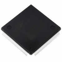
ST10F276Z5Q3 STMicroelectronics, ST10F276Z5Q3 Datasheet - Page 113

ST10F276Z5Q3
Manufacturer Part Number
ST10F276Z5Q3
Description
MCU 16BIT 832KB FLASH 144-PQFP
Manufacturer
STMicroelectronics
Series
ST10r
Datasheet
1.ST10F276Z5T3.pdf
(239 pages)
Specifications of ST10F276Z5Q3
Core Processor
ST10
Core Size
16-Bit
Speed
64MHz
Connectivity
ASC, CAN, EBI/EMI, I²C, SSC, UART/USART
Peripherals
POR, PWM, WDT
Number Of I /o
111
Program Memory Size
832KB (832K x 8)
Program Memory Type
FLASH
Ram Size
68K x 8
Voltage - Supply (vcc/vdd)
4.5 V ~ 5.5 V
Data Converters
A/D 24x10b
Oscillator Type
Internal
Operating Temperature
-40°C ~ 125°C
Package / Case
144-QFP
Processor Series
ST10F27x
Core
ST10
Data Bus Width
16 bit
Data Ram Size
68 KB
Interface Type
CAN/I2C
Maximum Clock Frequency
64 MHz
Number Of Programmable I/os
111
Number Of Timers
5
Operating Supply Voltage
4.5 V to 5.5 V
Maximum Operating Temperature
+ 125 C
Mounting Style
SMD/SMT
Minimum Operating Temperature
- 40 C
On-chip Adc
24-ch x 10-bit
For Use With
497-6399 - KIT DEV STARTER ST10F276Z5
Lead Free Status / RoHS Status
Lead free / RoHS Compliant
Eeprom Size
-
Lead Free Status / Rohs Status
Lead free / RoHS Compliant
Other names
497-5580
Available stocks
Company
Part Number
Manufacturer
Quantity
Price
Company:
Part Number:
ST10F276Z5Q3
Manufacturer:
AD
Quantity:
230
Company:
Part Number:
ST10F276Z5Q3
Manufacturer:
STMicroelectronics
Quantity:
10 000
Company:
Part Number:
ST10F276Z5Q3TR
Manufacturer:
STMicroelectronics
Quantity:
10 000
ST10F276Z5
19.3
Note:
Synchronous reset (warm reset)
A synchronous reset is triggered when RSTIN pin is pulled low while RPD pin is at high
level. In order to properly activate the internal reset logic of the device, the RSTIN pin must
be held low, at least, during 4 TCL (2 periods of CPU clock): refer also to
details on minimum reset pulse duration. The I/O pins are set to high impedance and
RSTOUT pin is driven low. After RSTIN level is detected, a short duration of a maximum of
12 TCL (six periods of CPU clock) elapses, during which pending internal hold states are
cancelled and the current internal access cycle if any is completed. External bus cycle is
aborted. The internal pull-down of RSTIN pin is activated if bit BDRSTEN of SYSCON
register was previously set by software. Note that this bit is always cleared on power-on or
after a reset sequence.
Short and long synchronous reset
Once the first maximum 16 TCL are elapsed (4+12TCL), the internal reset sequence starts.
It is 1024 TCL cycles long: at the end of it, and after other 8TCL the level of RSTIN is
sampled (after the filter, see RSTF in the drawings): if it is already at high level, only Short
Reset is flagged (Refer to
recognized still low, the Long reset is flagged as well. The major difference between Long
and Short reset is that during the Long reset, also P0(15:13) become transparent, so it is
possible to change the clock options.
●
●
The same behavior just described, occurs also when unidirectional reset is selected and
RSTIN pin is held low till the end of the internal sequence (exactly 1024TCL + max 16 TCL)
and released exactly at that time.
When running with CPU frequency lower than 40 MHz, the minimum valid reset pulse to be
recognized by the CPU (4 TCL) could be longer than the minimum analog filter delay (50ns);
so it might happen that a short reset pulse is not filtered by the analog input filter, but on the
other hand it is not long enough to trigger a CPU reset (shorter than 4 TCL): this would
generate a FLASH reset but not a system reset. In this condition, the FLASH answers
If 8 TCL > 500 ns (F
If 8 TCL < 500 ns (F
or Long, depending on the real filter delay (between 50 and 500 ns) and the CPU
frequency (RSTF sampled High means Short reset, RSTF sampled Low means Long
reset). Note that in case a Long Reset is recognized, once the 8 TCL are elapsed, the
P0(15:13) pins becomes transparent, so the system clock can be re-configured. The
port returns not transparent 3-4TCL after the internal RSTF signal becomes high.
Warning:
In case of a short pulse on RSTIN pin, and when Bidirectional
reset is enabled, the RSTIN pin is held low by the internal
circuitry. At the end of the 1024 TCL cycles, the RTSIN pin is
released, but due to the presence of the input analog filter the
internal input reset signal (RSTF in the drawings) is released
later (from 50 to 500 ns). This delay is in parallel with the
additional 8 TCL, at the end of which the internal input reset
line (RSTF) is sampled, to decide if the reset event is Short or
Long. In particular:
CPU
CPU
Chapter 19: System reset
> 8 MHz), the reset event could be recognized either as Short
< 8 MHz), the reset event is always recognized as Short
for details on reset flags); if it is
Section 19.1
System reset
113/239
for


