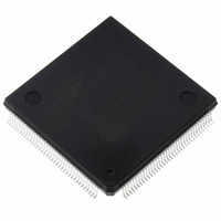
ST10F276Z5Q3 STMicroelectronics, ST10F276Z5Q3 Datasheet - Page 176

ST10F276Z5Q3
Manufacturer Part Number
ST10F276Z5Q3
Description
MCU 16BIT 832KB FLASH 144-PQFP
Manufacturer
STMicroelectronics
Series
ST10r
Datasheet
1.ST10F276Z5T3.pdf
(239 pages)
Specifications of ST10F276Z5Q3
Core Processor
ST10
Core Size
16-Bit
Speed
64MHz
Connectivity
ASC, CAN, EBI/EMI, I²C, SSC, UART/USART
Peripherals
POR, PWM, WDT
Number Of I /o
111
Program Memory Size
832KB (832K x 8)
Program Memory Type
FLASH
Ram Size
68K x 8
Voltage - Supply (vcc/vdd)
4.5 V ~ 5.5 V
Data Converters
A/D 24x10b
Oscillator Type
Internal
Operating Temperature
-40°C ~ 125°C
Package / Case
144-QFP
Processor Series
ST10F27x
Core
ST10
Data Bus Width
16 bit
Data Ram Size
68 KB
Interface Type
CAN/I2C
Maximum Clock Frequency
64 MHz
Number Of Programmable I/os
111
Number Of Timers
5
Operating Supply Voltage
4.5 V to 5.5 V
Maximum Operating Temperature
+ 125 C
Mounting Style
SMD/SMT
Minimum Operating Temperature
- 40 C
On-chip Adc
24-ch x 10-bit
For Use With
497-6399 - KIT DEV STARTER ST10F276Z5
Lead Free Status / RoHS Status
Lead free / RoHS Compliant
Eeprom Size
-
Lead Free Status / Rohs Status
Lead free / RoHS Compliant
Other names
497-5580
Available stocks
Company
Part Number
Manufacturer
Quantity
Price
Company:
Part Number:
ST10F276Z5Q3
Manufacturer:
AD
Quantity:
230
Company:
Part Number:
ST10F276Z5Q3
Manufacturer:
STMicroelectronics
Quantity:
10 000
Company:
Part Number:
ST10F276Z5Q3TR
Manufacturer:
STMicroelectronics
Quantity:
10 000
- Current page: 176 of 239
- Download datasheet (3Mb)
Register set
Note:
22.10.1
Note:
176/239
The default XPER selection after Reset is such that CAN1 is enabled, CAN2 is disabled,
XRAM1 (2 Kbyte XRAM) is enabled and XRAM2 (64 Kbyte XRAM) is disabled; all the other
X-Peripherals are disabled after Reset.
Register XPERCON cannot be changed after the global enabling of X-Peripherals, that is,
after setting of bit XPEN in SYSCON register.
In Emulation mode, all the X-Peripherals are enabled (XPERCON bits are all set). The
bondout chip determines whether or not to redirect an access to external memory or to
XBUS.
Reserved bits of XPERCON register are always written to ‘0’.
Table 87
during reset as well as the SYSCON (bit XPEN) and XPERCON (bits XRAM2EN and
XFLASHEN) registers user programmed values.
Table 87.
The symbol “x” in the table above stands for “do not care”.
XPERCON and XPEREMU registers
As already mentioned, the XPERCON register must be programmed to enable the single
XBUS modules separately. The XPERCON is a read/write ESFR register; the XPEREMU
register is a write-only register mapped on XBUS memory space (address EB7Eh).
Once the XPEN bit of SYSCON register is set and at least one of the X-peripherals (except
memories) is activated, the register XPEREMU must be written with the same content of
XPERCON: This is mandatory in order to allow a correct emulation of the new set of
features introduced on XBUS for the new ST10 generation. The following instructions must
be added inside the initialization routine:
Of course, XPEREMU must be programmed after XPERCON and after SYSCON; in this
way the final configuration for X-Peripherals is stored in XPEREMU and used for the
emulation hardware setup.
XPEREMU (EB7Eh)
The bit meaning is exactly the same as in XPERCON.
.
15
-
-
if (SYSCON.XPEN && (XPERCON & 0x07D3))
then { XPEREMU = XPERCON }
EA
0
0
0
0
1
14
-
-
below summarizes the Segment 8 mapping that depends upon the EA pin status
Segment 8 address range mapping
13
-
-
XPEN
12
-
-
0
1
1
1
x
11
-
-
XMISC
XRAM2EN
RW
10
EN
x
0
1
x
x
XI2C
RW
EN
9
XBUS
XSSC
RW
EN
8
XFLASHEN
XASC
RW
EN
x
0
x
1
x
7
XPWM
RW
EN
6
External memory
External memory
Reserved
Reserved
IFlash (B1F1)
XFLAS
HEN
RW
5
XRTC
RW
EN
4
Segment 8
XRAM2
RW
EN
3
Reset value xxxxh:
XRAM1
RW
EN
2
ST10F276Z5
CAN2
RW
EN
1
CAN1
RW
EN
0
Related parts for ST10F276Z5Q3
Image
Part Number
Description
Manufacturer
Datasheet
Request
R

Part Number:
Description:
MCU 16BIT 832K FLASH 144-LQFP
Manufacturer:
STMicroelectronics
Datasheet:

Part Number:
Description:
MCU 16BIT 832K FLASH 144-LQFP
Manufacturer:
STMicroelectronics
Datasheet:

Part Number:
Description:
MCU 16BIT 832K FLASH 144-PQFP
Manufacturer:
STMicroelectronics
Datasheet:

Part Number:
Description:
MCU 16BIT 832K FLASH 144-PQFP
Manufacturer:
STMicroelectronics
Datasheet:

Part Number:
Description:
16-bit Microcontrollers - MCU 16-Bit MCU 832 kByte 68 KB RAM CMOS
Manufacturer:
STMicroelectronics

Part Number:
Description:
STMicroelectronics [RIPPLE-CARRY BINARY COUNTER/DIVIDERS]
Manufacturer:
STMicroelectronics
Datasheet:

Part Number:
Description:
STMicroelectronics [LIQUID-CRYSTAL DISPLAY DRIVERS]
Manufacturer:
STMicroelectronics
Datasheet:

Part Number:
Description:
BOARD EVAL FOR MEMS SENSORS
Manufacturer:
STMicroelectronics
Datasheet:

Part Number:
Description:
NPN TRANSISTOR POWER MODULE
Manufacturer:
STMicroelectronics
Datasheet:

Part Number:
Description:
TURBOSWITCH ULTRA-FAST HIGH VOLTAGE DIODE
Manufacturer:
STMicroelectronics
Datasheet:

Part Number:
Description:
Manufacturer:
STMicroelectronics
Datasheet:

Part Number:
Description:
DIODE / SCR MODULE
Manufacturer:
STMicroelectronics
Datasheet:


