C8051F521A-IM Silicon Laboratories Inc, C8051F521A-IM Datasheet - Page 60
C8051F521A-IM
Manufacturer Part Number
C8051F521A-IM
Description
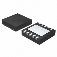
IC 8051 MCU 8K FLASH 10DFN
Manufacturer
Silicon Laboratories Inc
Series
C8051F52xr
Specifications of C8051F521A-IM
Program Memory Type
FLASH
Program Memory Size
8KB (8K x 8)
Package / Case
10-DFN
Core Processor
8051
Core Size
8-Bit
Speed
25MHz
Connectivity
SPI, UART/USART
Peripherals
Brown-out Detect/Reset, POR, PWM, Temp Sensor, WDT
Number Of I /o
6
Ram Size
256 x 8
Voltage - Supply (vcc/vdd)
1.8 V ~ 5.25 V
Data Converters
A/D 6x12b
Oscillator Type
Internal
Operating Temperature
-40°C ~ 125°C
Processor Series
C8051F5x
Core
8051
Data Bus Width
8 bit
Data Ram Size
256 B
Interface Type
SPI/UART
Maximum Clock Frequency
25 MHz
Number Of Programmable I/os
6
Number Of Timers
3
Maximum Operating Temperature
+ 125 C
Mounting Style
SMD/SMT
3rd Party Development Tools
PK51, CA51, A51, ULINK2
Development Tools By Supplier
C8051F500DK
Minimum Operating Temperature
- 40 C
On-chip Adc
6-ch x 12-bit
Lead Free Status / RoHS Status
Lead free / RoHS Compliant
For Use With
336-1488 - KIT DEV C8051F53XA, C8051F52XA770-1006 - ISP 4PORT FOR SILABS C8051F MCU336-1455 - ADAPTER PROGRAM TOOLSTICK F520
Eeprom Size
-
Lead Free Status / Rohs Status
Lead free / RoHS Compliant
Other names
336-1490-5


C8051F52x/F52xA/F53x/F53xA
4.3.6. Settling Time Requirements
A minimum tracking time is required before an accurate conversion can be performed. This tracking time is
determined by the AMUX0 resistance, the ADC0 sampling capacitance, any external source resistance,
and the accuracy required for the conversion.
Figure 4.6 shows the equivalent ADC0 input circuit. The required ADC0 settling time for a given settling
accuracy (SA) may be approximated by Equation 4.1. When measuring the Temperature Sensor output,
use the settling time specified in Table 2.3 on page 29. See Table 2.3 on page 29 for ADC0 minimum set-
tling time requirements.
Where:
SA is the settling accuracy, given as a fraction of an LSB (for example, 0.25 to settle within 1/4 LSB)
t is the required settling time in seconds
R
n is the ADC resolution in bits (12).
4.4. Selectable Gain
ADC0 on the C8051F52x/52xA/53x/53xA family of devices implements a selectable gain adjustment
option. By writing a value to the gain adjust address range, the user can select gain values between 0 and
1.016.
For example, three analog sources to be measured have full-scale outputs of 5.0 V, 4.0 V, and 3.0 V,
respectively. Each ADC measurement would ideally use the full dynamic range of the ADC with an internal
voltage reference of 1.5 V or 2.2 V (set to 2.2 V for this example). When selecting signal one (5.0 V full-
scale), a gain value of 0.44 (5 V full scale * 0.44 = 2.2 V full scale) provides a full-scale signal of 2.2 V
when the input signal is 5.0 V. Likewise, a gain value of 0.55 (4 V full scale * 0.55 = 2.2 V full scale) for the
second source and 0.73 (3 V full scale * 0.73 = 2.2 V full scale) for the third source provide full-scale ADC0
measurements when the input signal is full-scale.
Additionally, some sensors or other input sources have small part-to-part variations that must be
accounted for to achieve accurate results. In this case, the programmable gain value could be used as a
calibration value to eliminate these part-to-part variations.
60
TOTAL
is the sum of the AMUX0 resistance and any external source resistance.
Equation 4.1. ADC0 Settling Time Requirements
Figure 4.6. ADC0 Equivalent Input Circuits
Px.x
t
=
ln
R C
------ -
SA
2
M U X S elect
Inp u t
n
= R
Rev. 1.3
R
M U X
TOTAL
* C
R
M U X
S A M P L E
C
SAMPLE
C
S A M P LE
Related parts for C8051F521A-IM
Image
Part Number
Description
Manufacturer
Datasheet
Request
R

Part Number:
Description:
SMD/C°/SINGLE-ENDED OUTPUT SILICON OSCILLATOR
Manufacturer:
Silicon Laboratories Inc
Part Number:
Description:
Manufacturer:
Silicon Laboratories Inc
Datasheet:
Part Number:
Description:
N/A N/A/SI4010 AES KEYFOB DEMO WITH LCD RX
Manufacturer:
Silicon Laboratories Inc
Datasheet:
Part Number:
Description:
N/A N/A/SI4010 SIMPLIFIED KEY FOB DEMO WITH LED RX
Manufacturer:
Silicon Laboratories Inc
Datasheet:
Part Number:
Description:
N/A/-40 TO 85 OC/EZLINK MODULE; F930/4432 HIGH BAND (REV E/B1)
Manufacturer:
Silicon Laboratories Inc
Part Number:
Description:
EZLink Module; F930/4432 Low Band (rev e/B1)
Manufacturer:
Silicon Laboratories Inc
Part Number:
Description:
I°/4460 10 DBM RADIO TEST CARD 434 MHZ
Manufacturer:
Silicon Laboratories Inc
Part Number:
Description:
I°/4461 14 DBM RADIO TEST CARD 868 MHZ
Manufacturer:
Silicon Laboratories Inc
Part Number:
Description:
I°/4463 20 DBM RFSWITCH RADIO TEST CARD 460 MHZ
Manufacturer:
Silicon Laboratories Inc
Part Number:
Description:
I°/4463 20 DBM RADIO TEST CARD 868 MHZ
Manufacturer:
Silicon Laboratories Inc
Part Number:
Description:
I°/4463 27 DBM RADIO TEST CARD 868 MHZ
Manufacturer:
Silicon Laboratories Inc
Part Number:
Description:
I°/4463 SKYWORKS 30 DBM RADIO TEST CARD 915 MHZ
Manufacturer:
Silicon Laboratories Inc
Part Number:
Description:
N/A N/A/-40 TO 85 OC/4463 RFMD 30 DBM RADIO TEST CARD 915 MHZ
Manufacturer:
Silicon Laboratories Inc
Part Number:
Description:
I°/4463 20 DBM RADIO TEST CARD 169 MHZ
Manufacturer:
Silicon Laboratories Inc