MC9S08RD32PE Freescale Semiconductor, MC9S08RD32PE Datasheet - Page 120
MC9S08RD32PE
Manufacturer Part Number
MC9S08RD32PE
Description
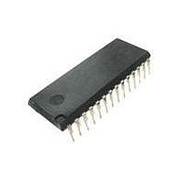
IC MCU 32K FLASH 2K RAM 28-DIP
Manufacturer
Freescale Semiconductor
Series
HCS08r
Datasheet
1.MC9S08RE8FJE.pdf
(234 pages)
Specifications of MC9S08RD32PE
Core Processor
HCS08
Core Size
8-Bit
Speed
8MHz
Connectivity
SCI
Peripherals
LVD, POR, PWM, WDT
Number Of I /o
23
Program Memory Size
32KB (32K x 8)
Program Memory Type
FLASH
Ram Size
2K x 8
Voltage - Supply (vcc/vdd)
1.8 V ~ 3.6 V
Oscillator Type
Internal
Operating Temperature
0°C ~ 70°C
Package / Case
28-DIP (0.600", 15.24mm)
Processor Series
S08RD
Core
HCS08
Data Bus Width
8 bit
Data Ram Size
2 KB
Interface Type
SCI
Maximum Clock Frequency
8 MHz
Number Of Programmable I/os
39
Number Of Timers
2
Operating Supply Voltage
1.8 V to 3.6 V
Maximum Operating Temperature
+ 70 C
Mounting Style
Through Hole
3rd Party Development Tools
EWS08
Development Tools By Supplier
DEMO9S08RG60E
Minimum Operating Temperature
0 C
Lead Free Status / RoHS Status
Lead free / RoHS Compliant
Eeprom Size
-
Data Converters
-
Lead Free Status / Rohs Status
Lead free / RoHS Compliant
Available stocks
Company
Part Number
Manufacturer
Quantity
Price
Company:

Part Number:
MC9S08RD32PE
Manufacturer:
Freescale Semiconductor
Quantity:
135


Carrier Modulator Transmitter (CMT) Block Description
8.6.2
This register is used to control the IRO output of the CMT module.
120
CMTPOL
IROPEN
SL[7:0]
Field
Field
IROL
7:0
7
6
5
Reset
Reset
W
W
R
R
u = Unaffected
CMT Output Control Register (CMTOC)
Secondary Carrier Low Time Data Values — When selected, these bits contain the number of input clocks
required to generate the carrier high and low time periods. When operating in time mode (see
“Time
Mode"), this register pair and the primary register pair are alternatively selected under control of the modulator.
The secondary carrier high and low time values are unaffected out of reset. These bits must be written to nonzero
values before the carrier generator is enabled when operating in FSK mode.
IRO Latch Control — Reading IROL reads the state of the IRO latch. Writing IROL changes the state of the IRO
pin when the MCGEN bit is clear in the CMTMSC register and the IROPEN bit is set.
CMT Output Polarity — The CMTPOL bit controls the polarity of the IRO pin output of the CMT.
0 IRO pin is active low
1 IRO pin is active high
IRO Pin Enable — The IROPEN bit is used to enable and disable the IRO pin. When the pin is enabled, it is an
output that drives out either the CMT transmitter output or the state of the IROL bit depending on whether the
MCGEN bit in the CMTMSC register is set. Also, the state of the output is either inverted or not depending on
the state of the CMTPOL bit. When the pin is disabled, it is in a high impedance state so it doesn’t draw any
current. The pin is disabled during reset.
0 IRO pin disabled
1 IRO pin enabled as output
IROL
SL7
u
0
7
7
Mode"), this register pair is never selected. When operating in FSK mode (see
Figure 8-11. Carrier Generator Data Register Low 2 (CMTCGL2)
= Unimplemented or Reserved
CMTPOL
Figure 8-12. CMT Output Control Register (CMTOC)
SL6
6
u
6
0
MC9S08RC/RD/RE/RG Data Sheet, Rev. 1.11
Table 8-6. CMTCGL2 Field Descriptions
Table 8-7. CMTOC Field Descriptions
IROPEN
SL5
u
0
5
5
SL4
4
u
4
0
0
Description
Description
SL3
u
0
0
3
3
SL2
2
u
2
0
0
Section 8.5.2.3, “FSK
Freescale Semiconductor
SL1
u
0
0
1
1
Section 8.5.2.1,
SL0
0
u
0
0
0
Related parts for MC9S08RD32PE
Image
Part Number
Description
Manufacturer
Datasheet
Request
R

Part Number:
Description:
Manufacturer:
Freescale Semiconductor, Inc
Datasheet:
Part Number:
Description:
Manufacturer:
Freescale Semiconductor, Inc
Datasheet:
Part Number:
Description:
Manufacturer:
Freescale Semiconductor, Inc
Datasheet:
Part Number:
Description:
Manufacturer:
Freescale Semiconductor, Inc
Datasheet:
Part Number:
Description:
Manufacturer:
Freescale Semiconductor, Inc
Datasheet:
Part Number:
Description:
Manufacturer:
Freescale Semiconductor, Inc
Datasheet:
Part Number:
Description:
Manufacturer:
Freescale Semiconductor, Inc
Datasheet:
Part Number:
Description:
Manufacturer:
Freescale Semiconductor, Inc
Datasheet:
Part Number:
Description:
Manufacturer:
Freescale Semiconductor, Inc
Datasheet:
Part Number:
Description:
Manufacturer:
Freescale Semiconductor, Inc
Datasheet:
Part Number:
Description:
Manufacturer:
Freescale Semiconductor, Inc
Datasheet:
Part Number:
Description:
Manufacturer:
Freescale Semiconductor, Inc
Datasheet:
Part Number:
Description:
Manufacturer:
Freescale Semiconductor, Inc
Datasheet:
Part Number:
Description:
Manufacturer:
Freescale Semiconductor, Inc
Datasheet:
Part Number:
Description:
Manufacturer:
Freescale Semiconductor, Inc
Datasheet: