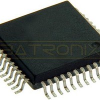
MC908AP32ACFBER Freescale Semiconductor, MC908AP32ACFBER Datasheet - Page 51

MC908AP32ACFBER
Manufacturer Part Number
MC908AP32ACFBER
Description
IC MCU 32K FLASH 8MHZ 44-QFP
Manufacturer
Freescale Semiconductor
Series
HC08r
Datasheet
1.MC908AP16ACFBER.pdf
(316 pages)
Specifications of MC908AP32ACFBER
Core Processor
HC08
Core Size
8-Bit
Speed
8MHz
Connectivity
I²C, IRSCI, SCI, SPI
Peripherals
LED, LVD, POR, PWM
Number Of I /o
32
Program Memory Size
32KB (32K x 8)
Program Memory Type
FLASH
Ram Size
2K x 8
Voltage - Supply (vcc/vdd)
4.5 V ~ 5.5 V
Data Converters
A/D 8x10b
Oscillator Type
Internal
Operating Temperature
-40°C ~ 85°C
Package / Case
44-QFP
Processor Series
HC08AP
Core
HC08
Data Bus Width
8 bit
Data Ram Size
2 KB
Interface Type
SCI, SPI
Maximum Clock Frequency
8 MHz
Number Of Programmable I/os
32
Number Of Timers
4
Maximum Operating Temperature
+ 85 C
Mounting Style
SMD/SMT
Development Tools By Supplier
FSICEBASE, DEMO908AP64E, M68CBL05CE
Minimum Operating Temperature
- 40 C
On-chip Adc
10 bit, 8 Channel
Lead Free Status / RoHS Status
Lead free / RoHS Compliant
Eeprom Size
-
Lead Free Status / Rohs Status
Details
Available stocks
Company
Part Number
Manufacturer
Quantity
Price
Company:
Part Number:
MC908AP32ACFBER
Manufacturer:
Freescale Semiconductor
Quantity:
10 000
- Current page: 51 of 316
- Download datasheet (2Mb)
LVIPWRD — V
LVIREGD — V
SSREC — Short Stop Recovery Bit
STOP — STOP Instruction Enable Bit
COPD — COP Disable Bit
Freescale Semiconductor
LVIPWRD disables the V
LVIREGD disables the V
SSREC enables the CPU to exit stop mode with a delay of 32 ICLK cycles instead of a 4096 ICLK
cycle delay.
STOP enables the STOP instruction.
COPD disables the COP module. (See
1 = V
0 = V
1 = V
0 = V
1 = Stop mode recovery after 32 ICLK cycles
0 = Stop mode recovery after 4096 ICLK cycles
1 = STOP instruction enabled
0 = STOP instruction treated as illegal opcode
1 = COP module disabled
0 = COP module enabled
DD
DD
REG
REG
LVI circuit disabled
LVI circuit enabled
If LVIPWRD=1 and LVIREGD=1, set LVIRSTD=1 before entering stop
mode.
Exiting stop mode by pulling reset will result in the long stop recovery.
If using an external crystal oscillator, do not set the SSREC bit.
When the LVI is disabled in stop mode (LVISTOP=0), the system
stabilization time for long stop recovery (4096 ICLK cycles) gives a delay
longer than the LVI’s turn-on time. There is no period where the MCU is not
protected from a low power condition. However, when using the short stop
recovery configuration option, the 32 ICLK delay is less than the LVI’s
turn-on time and there exists a period in start-up where the LVI is not
protecting the MCU.
REG
DD
LVI circuit disabled
LVI circuit enabled
LVI Circuit Disable Bit
LVI Circuit Disable Bit
REG
DD
LVI circuit. (See
LVI circuit. (See
MC68HC908AP A-Family Data Sheet, Rev. 3
Chapter 19 Computer Operating Properly
Chapter 20 Low-Voltage Inhibit
NOTE
NOTE
Chapter 20 Low-Voltage Inhibit
Configuration Register 1 (CONFIG1)
(LVI).)
(LVI).)
(COP).)
51
Related parts for MC908AP32ACFBER
Image
Part Number
Description
Manufacturer
Datasheet
Request
R
Part Number:
Description:
Manufacturer:
Freescale Semiconductor, Inc
Datasheet:
Part Number:
Description:
Manufacturer:
Freescale Semiconductor, Inc
Datasheet:
Part Number:
Description:
Manufacturer:
Freescale Semiconductor, Inc
Datasheet:
Part Number:
Description:
Manufacturer:
Freescale Semiconductor, Inc
Datasheet:
Part Number:
Description:
Manufacturer:
Freescale Semiconductor, Inc
Datasheet:
Part Number:
Description:
Manufacturer:
Freescale Semiconductor, Inc
Datasheet:
Part Number:
Description:
Manufacturer:
Freescale Semiconductor, Inc
Datasheet:
Part Number:
Description:
Manufacturer:
Freescale Semiconductor, Inc
Datasheet:
Part Number:
Description:
Manufacturer:
Freescale Semiconductor, Inc
Datasheet:
Part Number:
Description:
Manufacturer:
Freescale Semiconductor, Inc
Datasheet:
Part Number:
Description:
Manufacturer:
Freescale Semiconductor, Inc
Datasheet:
Part Number:
Description:
Manufacturer:
Freescale Semiconductor, Inc
Datasheet:
Part Number:
Description:
Manufacturer:
Freescale Semiconductor, Inc
Datasheet:
Part Number:
Description:
Manufacturer:
Freescale Semiconductor, Inc
Datasheet:
Part Number:
Description:
Manufacturer:
Freescale Semiconductor, Inc
Datasheet:


