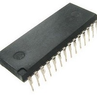
MC705P6ECPE Freescale Semiconductor, MC705P6ECPE Datasheet - Page 19

MC705P6ECPE
Manufacturer Part Number
MC705P6ECPE
Description
IC MCU 8BIT EPROM 28-DIP
Manufacturer
Freescale Semiconductor
Series
HC05r
Datasheet
1.MC705P6ACDWE.pdf
(98 pages)
Specifications of MC705P6ECPE
Core Processor
HC05
Core Size
8-Bit
Speed
2.1MHz
Connectivity
SIO
Peripherals
POR, WDT
Number Of I /o
21
Program Memory Size
4.5KB (4.5K x 8)
Program Memory Type
OTP
Ram Size
176 x 8
Voltage - Supply (vcc/vdd)
3 V ~ 5.5 V
Data Converters
A/D 4x8b
Oscillator Type
Internal
Operating Temperature
-40°C ~ 85°C
Package / Case
28-DIP (0.600", 15.24mm)
Processor Series
HC705P
Core
HC05
Data Bus Width
8 bit
Data Ram Size
176 B
Interface Type
SIOP
Maximum Clock Frequency
4.2 MHz
Number Of Programmable I/os
21
Number Of Timers
1
Operating Supply Voltage
- 0.3 V to + 7 V
Maximum Operating Temperature
+ 85 C
Mounting Style
Through Hole
Minimum Operating Temperature
- 40 C
On-chip Adc
8 bit, 4 Channel
On-chip Dac
8 bit, 4 Channel
Lead Free Status / RoHS Status
Lead free / RoHS Compliant
Eeprom Size
-
Lead Free Status / Rohs Status
Details
Available stocks
Company
Part Number
Manufacturer
Quantity
Price
Company:
Part Number:
MC705P6ECPE
Manufacturer:
Freescale Semiconductor
Quantity:
135
Chapter 2
Memory
2.1 Introduction
The MC68HC705P6A utilizes 13 address lines to access an internal memory space covering 8 Kbytes.
This memory space is divided into I/O, RAM, ROM, and EPROM areas.
2.2 User Mode Memory Map
When the MC68HC705P6A is in the user mode, the 32 bytes of I/O, 176 bytes of RAM, 4608 bytes of user
EPROM, 48 bytes of user page zero EPROM, 239 bytes of bootloader ROM, and 16 bytes of user vectors
EPROM are all active as shown in
2.3 Bootloader Mode Memory Map
Memory space is identical to the user mode. See
2.4 Input/Output and Control Registers
Figure 2-2
Reading unimplemented bits will return unknown states, and writing unimplemented bits will be ignored.
2.5 RAM
The user RAM consists of 176 bytes (including the stack) at locations $0050 through $00FF. The stack
begins at address $00FF. The stack pointer can access 64 bytes of RAM from $00FF to $00C0.
2.6 EPROM/ROM
There are 4608 bytes of user EPROM at locations $0100 through $12FF, plus 48 bytes in user page zero
locations $0020 through $004F, and 16 additional bytes for user vectors at locations $1FF0 through
$1FFF. The bootloader ROM and vectors are at locations $1F01 through $1FEF.
Freescale Semiconductor
and
Using the stack area for data storage or temporary work locations requires
care to prevent it from being overwritten due to stacking from an interrupt
or subroutine call.
Figure 2-3
briefly describe the I/O and control registers at locations $0000–$001F.
MC68HC705P6A Advance Information Data Sheet, Rev. 2.1
Figure
2-1.
NOTE
Figure
2-1.
19


