HD64F3687GH Renesas Electronics America, HD64F3687GH Datasheet - Page 52
HD64F3687GH
Manufacturer Part Number
HD64F3687GH
Description
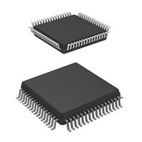
IC H8 MCU FLASH 56K 64-QFP
Manufacturer
Renesas Electronics America
Series
H8® H8/300H Tinyr
Datasheet
1.HD64F3684GFPV.pdf
(538 pages)
Specifications of HD64F3687GH
Core Processor
H8/300H
Core Size
16-Bit
Speed
20MHz
Connectivity
I²C, SCI
Peripherals
LVD, POR, PWM, WDT
Number Of I /o
45
Program Memory Size
56KB (56K x 8)
Program Memory Type
FLASH
Ram Size
4K x 8
Voltage - Supply (vcc/vdd)
3 V ~ 5.5 V
Data Converters
A/D 8x10b
Oscillator Type
Internal
Operating Temperature
-20°C ~ 75°C
Package / Case
64-QFP
Lead Free Status / RoHS Status
Contains lead / RoHS non-compliant
Eeprom Size
-
Available stocks
Company
Part Number
Manufacturer
Quantity
Price
Company:

Part Number:
HD64F3687GH
Manufacturer:
Renesas Electronics America
Quantity:
10 000
Company:
Part Number:
HD64F3687GHMV
Manufacturer:
Renesas Electronics America
Quantity:
10 000
Company:
Part Number:
HD64F3687GHV
Manufacturer:
ON
Quantity:
101
Company:
Part Number:
HD64F3687GHV
Manufacturer:
Renesas Electronics America
Quantity:
10 000
Part Number:
HD64F3687GHV
Manufacturer:
RENESAS/瑞萨
Quantity:
20 000


Section 2 CPU
Rev.5.00 Nov. 02, 2005 Page 18 of 500
REJ09B0027-0500
Bit
7
6
5
4
3
2
1
0
Bit Name
I
UI
H
U
N
Z
V
C
Initial
Value
1
Undefined R/W
Undefined R/W
Undefined R/W
Undefined R/W
Undefined R/W
Undefined R/W
Undefined R/W
R/W
R/W
Description
Interrupt Mask Bit
Masks interrupts other than NMI when set to 1. NMI is
accepted regardless of the I bit setting. The I bit is set
to 1 at the start of an exception-handling sequence.
User Bit
Can be written and read by software using the LDC,
STC, ANDC, ORC, and XORC instructions.
Half-Carry Flag
When the ADD.B, ADDX.B, SUB.B, SUBX.B, CMP.B,
or NEG.B instruction is executed, this flag is set to 1 if
there is a carry or borrow at bit 3, and cleared to 0
otherwise. When the ADD.W, SUB.W, CMP.W, or
NEG.W instruction is executed, the H flag is set to 1 if
there is a carry or borrow at bit 11, and cleared to 0
otherwise. When the ADD.L, SUB.L, CMP.L, or NEG.L
instruction is executed, the H flag is set to 1 if there is a
carry or borrow at bit 27, and cleared to 0 otherwise.
User Bit
Can be written and read by software using the LDC,
STC, ANDC, ORC, and XORC instructions.
Negative Flag
Stores the value of the most significant bit of data as a
sign bit.
Zero Flag
Set to 1 to indicate zero data, and cleared to 0 to
indicate non-zero data.
Overflow Flag
Set to 1 when an arithmetic overflow occurs, and
cleared to 0 at other times.
Carry Flag
Set to 1 when a carry occurs, and cleared to 0
otherwise. Used by:
The carry flag is also used as a bit accumulator by bit
manipulation instructions.
Add instructions, to indicate a carry
Subtract instructions, to indicate a borrow
Shift and rotate instructions, to indicate a carry
Related parts for HD64F3687GH
Image
Part Number
Description
Manufacturer
Datasheet
Request
R

Part Number:
Description:
(HD64 Series) Hitachi Single-Chip Microcomputer
Manufacturer:
Hitachi Semiconductor
Datasheet:

Part Number:
Description:
KIT STARTER FOR M16C/29
Manufacturer:
Renesas Electronics America
Datasheet:

Part Number:
Description:
KIT STARTER FOR R8C/2D
Manufacturer:
Renesas Electronics America
Datasheet:

Part Number:
Description:
R0K33062P STARTER KIT
Manufacturer:
Renesas Electronics America
Datasheet:

Part Number:
Description:
KIT STARTER FOR R8C/23 E8A
Manufacturer:
Renesas Electronics America
Datasheet:

Part Number:
Description:
KIT STARTER FOR R8C/25
Manufacturer:
Renesas Electronics America
Datasheet:

Part Number:
Description:
KIT STARTER H8S2456 SHARPE DSPLY
Manufacturer:
Renesas Electronics America
Datasheet:

Part Number:
Description:
KIT STARTER FOR R8C38C
Manufacturer:
Renesas Electronics America
Datasheet:

Part Number:
Description:
KIT STARTER FOR R8C35C
Manufacturer:
Renesas Electronics America
Datasheet:

Part Number:
Description:
KIT STARTER FOR R8CL3AC+LCD APPS
Manufacturer:
Renesas Electronics America
Datasheet:
Part Number:
Description:
KIT STARTER FOR RX610
Manufacturer:
Renesas Electronics America
Datasheet:

Part Number:
Description:
KIT STARTER FOR R32C/118
Manufacturer:
Renesas Electronics America
Datasheet:

Part Number:
Description:
KIT DEV RSK-R8C/26-29
Manufacturer:
Renesas Electronics America
Datasheet:

Part Number:
Description:
KIT STARTER FOR SH7124
Manufacturer:
Renesas Electronics America
Datasheet:

Part Number:
Description:
KIT STARTER FOR H8SX/1622
Manufacturer:
Renesas Electronics America
Datasheet: