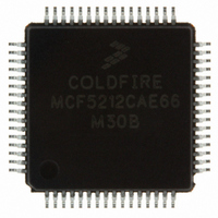
MCF5212CAE66 Freescale Semiconductor, MCF5212CAE66 Datasheet - Page 37

MCF5212CAE66
Manufacturer Part Number
MCF5212CAE66
Description
IC MCU 256K FLASH 66MHZ 64-LQFP
Manufacturer
Freescale Semiconductor
Series
MCF521xr
Datasheet
1.MCF5213CAF80.pdf
(54 pages)
Specifications of MCF5212CAE66
Core Processor
Coldfire V2
Core Size
32-Bit
Speed
66MHz
Connectivity
I²C, SPI, UART/USART
Peripherals
DMA, LVD, POR, PWM, WDT
Number Of I /o
55
Program Memory Size
256KB (256K x 8)
Program Memory Type
FLASH
Ram Size
32K x 8
Voltage - Supply (vcc/vdd)
3 V ~ 3.6 V
Data Converters
A/D 8x12b
Oscillator Type
Internal
Operating Temperature
-40°C ~ 85°C
Package / Case
64-LQFP
Processor Series
MCF521x
Core
ColdFire V2
Data Bus Width
32 bit
Data Ram Size
32 KB
Interface Type
I2C, QSPI, UART
Maximum Clock Frequency
80 MHz
Number Of Programmable I/os
56
Number Of Timers
10
Operating Supply Voltage
3 V to 3.6 V
Maximum Operating Temperature
+ 105 C
Mounting Style
SMD/SMT
3rd Party Development Tools
JLINK-CF-BDM26, EWCF
Development Tools By Supplier
M52210DEMO, M52211EVB
Minimum Operating Temperature
0 C
On-chip Adc
12 bit, 8 Channel
For Use With
M5211DEMO - KIT DEMO FOR MCF5211
Lead Free Status / RoHS Status
Lead free / RoHS Compliant
Eeprom Size
-
Lead Free Status / Rohs Status
Lead free / RoHS Compliant
Available stocks
Company
Part Number
Manufacturer
Quantity
Price
Company:
Part Number:
MCF5212CAE66
Manufacturer:
FREESCAL
Quantity:
1 210
Company:
Part Number:
MCF5212CAE66
Manufacturer:
Freescale Semiconductor
Quantity:
10 000
Part Number:
MCF5212CAE66
Manufacturer:
FREESCALE
Quantity:
20 000
2.13
Figure 10-17 shows the ADC input circuit during sample and hold. S1 and S2 are always open/closed at the same time that S3
is closed/open. When S1/S2 are closed & S3 is open, one input of the sample and hold circuit moves to (V
the other charges to the analog input voltage. When the switches are flipped, the charge on C1 and C2 are averaged via S3, with
the result that a single-ended analog input is switched to a differential voltage centered about (V
switch on every cycle of the ADC clock (open one-half ADC clock, closed one-half ADC clock). There are additional
capacitances associated with the analog input pad, routing, etc., but these do not filter into the S/H output voltage, as S1 provides
isolation during the charge-sharing phase. One aspect of this circuit is that there is an on-going input current, which is a function
of the analog input voltage, V
Freescale Semiconductor
1
2
3
4
5
6
7
V
V
All measurements are preliminary pending full characterization, and made at V
INL measured from V
LSB = Least Significant Bit
INL measured from V
Includes power-up of ADC and V
ADC clock cycles
Current that can be injected or sourced from an unselected ADC signal input without impacting the performance of the ADC
SINAD
I
ENOB
Name
SFDR
OFFSET
E
OFFSET
VREFH
SNR
THD
1.
2.
I
X
GAIN
ADI
IN
Parasitic capacitance due to package, pin-to-pin and pin-to-package base coupling; 1.8pF
Parasitic capacitance due to the chip bond pad, ESD protection devices and signal routing; 2.04pF
Analog Input
Equivalent Circuit for ADC Inputs
Spurious free dynamic range
Input impedance
Input injection current
V
Offset voltage internal reference
Gain error (transfer path)
Offset voltage external reference
Signal-to-noise ratio
Total harmonic distortion
Signal-to-noise plus distortion
Effective number of bits
REFH
1
current
IN
IN
= V
= 0.1V
REF
REFL
2
REFH
Characteristic
and the ADC clock frequency.
7
to V
REF
, per pin
to V
IN
Table 34. ADC Parameters
MCF5213 ColdFire Microcontroller, Rev. 4
= V
IN
REFH
= 0.9V
125W ESD Resistor
REFH
(V
REFH
3
- V
REFL
)/ 2
8pF noise damping capacitor
S1
1
(continued)
S2
Min
.99
9.1
—
—
—
—
—
—
—
—
—
DD
4
= 3.3V, V
S3
See
67 to 70.3
61 to 63.9
62 to 66
Typical
10.6
Figure 8
−75
±8
±3
C2
—
C1
0
1
REFH
REFH
S/H
= 3.3V, and V
Electrical Characteristics
-V
C1 = C2 = 1pF
Max
1.01
±15
REFL
REFH
—
—
—
—
—
—
—
3
9
)/2. The switches
-V
REFL
REFL
)/2, while
Unit
= ground
Bits
mA
mA
mV
mV
dB
dB
dB
dB
W
—
37


