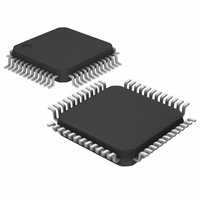
MAXQ7667AACM/V+T Maxim Integrated Products, MAXQ7667AACM/V+T Datasheet - Page 29

MAXQ7667AACM/V+T
Manufacturer Part Number
MAXQ7667AACM/V+T
Description
IC MCU-BASED DAS 16BIT 48-LQFP
Manufacturer
Maxim Integrated Products
Series
MAXQ™r
Datasheet
1.MAXQ7667AACMV.pdf
(40 pages)
Specifications of MAXQ7667AACM/V+T
Core Processor
RISC
Core Size
16-Bit
Speed
16MHz
Connectivity
LIN, SPI, UART/USART
Peripherals
Brown-out Detect/Reset, POR, WDT
Number Of I /o
16
Program Memory Size
32KB (16K x 16)
Program Memory Type
FLASH
Ram Size
2K x 16
Voltage - Supply (vcc/vdd)
2.25 V ~ 2.75 V
Data Converters
A/D 5x12b
Oscillator Type
Internal
Operating Temperature
-40°C ~ 125°C
Package / Case
48-LQFP
Processor Series
MAXQ7667
Core
RISC
Data Bus Width
16 bit
Data Ram Size
4 KB
Interface Type
UART, JTAG, LIN
Maximum Clock Frequency
16 MHz
Number Of Programmable I/os
16
Number Of Timers
3
Operating Supply Voltage
5 V
Maximum Operating Temperature
+ 125 C
Mounting Style
SMD/SMT
Development Tools By Supplier
MAXQ7667EVKIT
Minimum Operating Temperature
- 40 C
On-chip Adc
12 bit, 5 Channel
Lead Free Status / RoHS Status
Lead free / RoHS Compliant
Eeprom Size
-
Lead Free Status / Rohs Status
Details
the application code executes. The application codes
initiate reprogramming. If the password is not set, the
MAXQ7667 monitors the UART for an autobaud char-
acter (0x0D). If this character is received, the device
sets its serial baud rate and initiates a boot loader pro-
cedure. If 0x0D is not received after five seconds, the
device begins execution of the application code.
The following bootloader functions are supported:
The in-application programming feature allows the µC
to modify its own flash program memory while simulta-
neously executing its application software. This allows
on the fly software updates in mission-critical applica-
tions that cannot afford downtime. Erase and program
the flash memory using the flash programming func-
tions in the utility ROM. Refer to Section 18 of the
MAXQ7667 User’s Guide for a detailed description of
the utility ROM functions.
Power consumption reaches its minimum in stop mode
(STOP = 1). In this mode, the external oscillator, inter-
nal RC oscillator, system clock, and all processing
halts. Trigger an enabled external interrupt input or
directly apply an external reset on RESET to exit stop
mode. Upon exiting stop mode, the µC either waits for
the external high-frequency crystal to complete its
warmup period or starts execution immediately from its
internal RC oscillator while the crystal warms up.
Multiple interrupt sources quickly respond to internal
and external events. The MAXQ architecture uses a
single interrupt vector (IV) and single interrupt-service
routine (ISR) design. Enable interrupts globally,
• Load
• Dump
• CRC
• Verify
• Erase
______________________________________________________________________________________
Ultrasonic Distance-Measuring System
In-Application Programming
16-Bit, RISC, Microcontroller-Based,
Stop Mode
Interrupts
individually, or by module. When an interrupt condition
occurs, its individual flag is set even if the interrupt
source is disabled at the local, module, or global level.
Clear interrupt flags within the interrupt routine to avoid
repeated false interrupts from the same source.
Provide an adequate delay between the write to the
flag and the RETI instruction using application software
to allow time for the interrupt hardware to remove the
internal interrupt condition. Asynchronous interrupt
flags require a one-instruction delay and synchronous
interrupt flags require a two-instruction delay.
When an enabled interrupt is detected, software jumps
to a user-programmable interrupt vector location. The
IV register defaults to 0000h on reset or power-up.
Once software control transfers to the ISR, use the
interrupt identification register (IIR) to determine if the
source of the interrupt is a system register or peripheral
register. The specified module identifies the specific
interrupt source. The following interrupt sources are
available:
• Watchdog interrupt
• External interrupts 0–7 on port 0 and port 1
• Timer 0 low compare, low overflow, capture/com-
• Timer 1 low compare, low overflow, capture/com-
• Timer 2 low compare, low overflow, and overflow
• Schedule timer alarm interrupt
• SPI data transfer complete, mode fault, write colli-
• UART transmit, receive interrupts
• LIN mode master or slave interrupt
• SAR ADC data ready interrupt
• Echo envelope LPF output, FIFO full, and com-
• Digital and I/O voltage brownout interrupts
• High-frequency oscillator failure interrupt
pare, and overflow interrupts
pare, and overflow interrupts
interrupts
sion and receive overrun interrupts
parator interrupts
29


