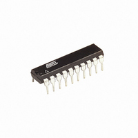
AT90S2313-4PC Atmel, AT90S2313-4PC Datasheet - Page 37

AT90S2313-4PC
Manufacturer Part Number
AT90S2313-4PC
Description
IC MCU 2K 4MHZ UART LV 20DIP
Manufacturer
Atmel
Series
AVR® 90Sr
Datasheet
1.AT90S2313-10PC.pdf
(92 pages)
Specifications of AT90S2313-4PC
Core Processor
AVR
Core Size
8-Bit
Speed
4MHz
Connectivity
SPI, UART/USART
Peripherals
Brown-out Detect/Reset, POR, PWM, WDT
Number Of I /o
15
Program Memory Size
2KB (1K x 16)
Program Memory Type
FLASH
Eeprom Size
128 x 8
Ram Size
128 x 8
Voltage - Supply (vcc/vdd)
2.7 V ~ 6 V
Oscillator Type
External
Operating Temperature
0°C ~ 70°C
Package / Case
20-DIP (0.300", 7.62mm)
Data Bus Width
8 bit
Data Ram Size
128 B
Interface Type
SPI, UART
Maximum Clock Frequency
4 MHz
Number Of Programmable I/os
15
Number Of Timers
1 x 16 bit
Operating Supply Voltage
2.7 V to 6 V
Maximum Operating Temperature
+ 70 C
Mounting Style
Through Hole
Minimum Operating Temperature
0 C
Lead Free Status / RoHS Status
Contains lead / RoHS non-compliant
Data Converters
-
Lead Free Status / Rohs Status
No
Available stocks
Company
Part Number
Manufacturer
Quantity
Price
Company:
Part Number:
AT90S2313-4PC
Manufacturer:
ATMEL
Quantity:
5 530
Watchdog Timer
Watchdog Timer Control
Register – WDTCR
0839I–AVR–06/02
The Watchdog Timer is clocked from a separate On-chip Oscillator that runs at 1 MHz.
This is the typical value at V
V
can be adjusted. See Table 14 for a detailed description. The WDR (Watchdog Reset)
instruction resets the Watchdog Timer. Eight different clock cycle periods can be
selected to determine the reset period. If the reset period expires without another
Watchdog Reset, the AT90S2313 resets and executes from the Reset Vector. For tim-
ing details on the Watchdog Reset, refer to page 21.
To prevent unintentional disabling of the Watchdog, a special turn-off sequence must be
followed when the Watchdog is disabled. Refer to the description of the Watchdog Timer
Control Register for details.
Figure 33. Watchdog Timer
• Bits 7..5 – Res: Reserved Bits
These bits are reserved bits in the AT90S2313 and will always read as zero.
• Bit 4 – WDTOE: Watchdog Turn-off Enable
This bit must be set (one) when the WDE bit is cleared. Otherwise, the Watchdog will
not be disabled. Once set, hardware will clear this bit to zero after four clock cycles.
Refer to the description of the WDE bit for a Watchdog disable procedure.
• Bit 3 – WDE: Watchdog Enable
When the WDE is set (one) the Watchdog Timer is enabled, and if the WDE is cleared
(zero), the Watchdog Timer function is disabled. WDE can only be cleared if the
WDTOE bit is set (one). To disable an enabled Watchdog Timer, the following proce-
dure must be followed:
Bit
$21 ($41)
Read/Write
Initial value
CC
levels. By controlling the Watchdog Timer prescaler, the Watchdog Reset interval
R
7
–
0
R
6
–
0
CC
= 5V. See characterization data for typical values at other
R
5
–
0
WDTOE
R/W
4
0
WDE
R/W
3
0
WDP2
R/W
2
0
WDP1
R/W
1
0
AT90S2313
WDP0
R/W
0
0
WDTCR
37


