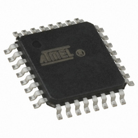
ATTINY28V-1AC Atmel, ATTINY28V-1AC Datasheet - Page 19

ATTINY28V-1AC
Manufacturer Part Number
ATTINY28V-1AC
Description
IC AVR MCU 2K 1.2MHZ 1.8V 32TQFP
Manufacturer
Atmel
Series
AVR® ATtinyr
Specifications of ATTINY28V-1AC
Core Processor
AVR
Core Size
8-Bit
Speed
1.2MHz
Peripherals
POR, WDT
Number Of I /o
11
Program Memory Size
2KB (1K x 16)
Program Memory Type
FLASH
Voltage - Supply (vcc/vdd)
1.8 V ~ 5.5 V
Oscillator Type
Internal
Operating Temperature
0°C ~ 70°C
Package / Case
32-TQFP, 32-VQFP
Lead Free Status / RoHS Status
Contains lead / RoHS non-compliant
Eeprom Size
-
Ram Size
-
Data Converters
-
Connectivity
-
Available stocks
Company
Part Number
Manufacturer
Quantity
Price
Register Description
MCU Control and Status
Register – MCUCS
1062F–AVR–07/06
The MCU Control and Status Register contains control and status bits for general MCU
functions.
• Bit 7 – PLUPB: Pull-up Enable Port B
When the PLUPB bit is set (one), pull-up resistors are enabled on all Port B input pins.
When PLUPB is cleared, the pull-ups are disabled. If any of the special functions of Port
B is enabled, the corresponding pull-up(s) is disabled, independent of the value of
PLUPB.
• Bit 6 – Res: Reserved Bit
This bit is a reserved bit in the ATtiny28 and always reads as zero.
• Bit 5 – SE: Sleep Enable
The SE bit must be set (one) to make the MCU enter the sleep mode when the SLEEP
instruction is executed. To avoid the MCU entering the sleep mode unless it is the pro-
grammer’s purpose, it is recommended to set the Sleep Enable SE bit just before the
execution of the SLEEP instruction.
• Bit 4 – SM: Sleep Mode
This bit selects between the two available sleep modes. When SM is cleared (zero), Idle
Mode is selected as sleep mode. When SM is set (one), Power-down mode is selected
as sleep mode. For details, refer to “Sleep Modes” below.
• Bit 3 – WDRF: Watchdog Reset Flag
This bit is set if a Watchdog reset occurs. The bit is cleared by a Power-on Reset, or by
writing a logical “0” to the flag.
• Bit 2 – Res: Reserved Bit
This bit is a reserved bit in the ATtiny28 and always reads as zero.
• Bit 1 – EXTRF: External Reset Flag
This bit is set if an external reset occurs. The bit is cleared by a Power-on Reset, or by
writing a logical “0” to the flag.
• Bit 0 – PORF: Power-on Reset Flag
This bit is set if a Power-on Reset occurs. The bit is cleared by writing a logical “0” to the
flag.
To make use of the reset flags to identify a reset condition, the user should read and
then clear the flag bits in MCUCS as early as possible in the program. If the register is
cleared before another reset occurs, the source of the reset can be found by examining
the reset flags.
Bit
$07
Read/Write
Initial Value
PLUPB
R/W
7
0
R
6
–
0
R/W
SE
5
0
R/W
SM
4
0
See Bit
WDRF
Desc.
R/W
3
R
2
–
0
ATtiny28L/V
EXTRF
See Bit Description
R/W
1
PORF
R/W
0
MCUCS
19


