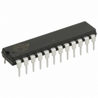
CY7C60223-PXC Cypress Semiconductor Corp, CY7C60223-PXC Datasheet - Page 28

CY7C60223-PXC
Manufacturer Part Number
CY7C60223-PXC
Description
IC MCU 8K WIRELESS 24-DIP
Manufacturer
Cypress Semiconductor Corp
Series
enCoRe™ II CY7C602xxr
Datasheet
1.CY7C60123-PVXC.pdf
(68 pages)
Specifications of CY7C60223-PXC
Core Processor
M8C
Core Size
8-Bit
Speed
12MHz
Connectivity
SPI
Peripherals
LVD, POR, WDT
Number Of I /o
20
Program Memory Size
8KB (8K x 8)
Program Memory Type
FLASH
Ram Size
256 x 8
Voltage - Supply (vcc/vdd)
2.7 V ~ 3.6 V
Oscillator Type
Internal
Operating Temperature
0°C ~ 70°C
Package / Case
24-DIP (0.300", 7.62mm)
For Use With
770-1001 - ISP 4PORT CYPRESS ENCORE II MCUCY3216 - KIT PROGRAMMER MODULAR428-1774 - EXTENSION KIT FOR ENCORE II428-1773 - KIT DEVELOPMENT ENCORE II
Lead Free Status / RoHS Status
Lead free / RoHS Compliant
Eeprom Size
-
Data Converters
-
Other names
428-1797
Available stocks
Company
Part Number
Manufacturer
Quantity
Price
Company:
Part Number:
CY7C60223-PXC
Manufacturer:
TEXAS
Quantity:
93
12.2.4 Internal Clock Trim
Table 12-1. IOSC Trim (IOSCTR) [0x34] [R/W]
12.2.5 External Clock Trim
Table 12-2. XOSC Trim (XOSCTR) [0x35] [R/W]
Document 38-16016 Rev. *F
The IOSC Calibrate Register is used to calibrate the internal oscillator. The reset value is undefined, but during boot the SROM
writes a calibration value that is determined during manufacturing test. The ‘D’ indicates that the default value is trimmed to
24 MHz at 3.30V at power on.
Bit [7:5]: foffset [2:0]
This value is used to trim the frequency of the internal oscillator. These bits are not used in factory calibration and is zero. Setting
each of these bits causes the appropriate fine offset in oscillator frequency.
foffset bit 0 = 7.5 kHz
foffset bit 1 = 15 kHz
foffset bit 2 = 30 kHz
Bit [4:0]: Gain [4:0]
The effective frequency change of the offset input is controlled through the gain input. A lower value of the gain setting increases
the gain of the offset input. This value sets the size of each offset step for the internal oscillator. Nominal gain change
(kHz/offsetStep) at each bit, typical conditions (24 MHz operation):
Gain bit 0 = –1.5 kHz
Gain bit 1 = –3.0 kHz
Gain bit 2 = –6 kHz
Gain bit 3 = –12 kHz
Gain bit 4 = –24 kHz
This register is used to calibrate the external crystal oscillator. The reset value is undefined, but during boot the SROM writes a
calibration value that is determined during manufacturing test. This is the meaning of ‘D’ in the Default field.
Bit [7:5]: Reserved
Bit [4:2]: XOSC XGM [2:0]
Amplifier transconductance setting. The Xgm settings are recommended for resonators with frequencies of interest for the
enCoRe II LV as below:
Bit 1: Reserved
Bit 0: Mode
0 = Oscillator Mode
1 = Fixed Maximum Bias Test Mode
Read/Write
Read/Write
12 MHz Ceramic
6 MHz Ceramic
12 MHz Crystal
Default
Default
6 MHz Crystal
Field
Field
Bit #
Bit #
Resonator
Reserved
R/W
7
0
7
–
0
XGM Setting
001
011
001
011
111
foffset[2:0]
Reserved
R/W
6
0
6
–
0
Worst Case R (Ohms)
R/W
5
0
5
–
0
70.4
403
201
41
-
R/W
R/W
D
D
4
4
XOSC XGM [2:0]
R/W
R/W
D
D
3
3
Gain[4:0]
R/W
R/W
CY7C601xx, CY7C602xx
D
D
2
2
Reserved
R/W
D
1
1
–
–
Page 28 of 68
Mode
R/W
R/W
D
D
0
0
[+] Feedback


