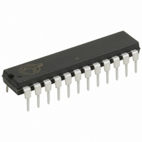
CY7C60223-PXC Cypress Semiconductor Corp, CY7C60223-PXC Datasheet - Page 47

CY7C60223-PXC
Manufacturer Part Number
CY7C60223-PXC
Description
IC MCU 8K WIRELESS 24-DIP
Manufacturer
Cypress Semiconductor Corp
Series
enCoRe™ II CY7C602xxr
Datasheet
1.CY7C60123-PVXC.pdf
(68 pages)
Specifications of CY7C60223-PXC
Core Processor
M8C
Core Size
8-Bit
Speed
12MHz
Connectivity
SPI
Peripherals
LVD, POR, WDT
Number Of I /o
20
Program Memory Size
8KB (8K x 8)
Program Memory Type
FLASH
Ram Size
256 x 8
Voltage - Supply (vcc/vdd)
2.7 V ~ 3.6 V
Oscillator Type
Internal
Operating Temperature
0°C ~ 70°C
Package / Case
24-DIP (0.300", 7.62mm)
For Use With
770-1001 - ISP 4PORT CYPRESS ENCORE II MCUCY3216 - KIT PROGRAMMER MODULAR428-1774 - EXTENSION KIT FOR ENCORE II428-1773 - KIT DEVELOPMENT ENCORE II
Lead Free Status / RoHS Status
Lead free / RoHS Compliant
Eeprom Size
-
Data Converters
-
Other names
428-1797
Available stocks
Company
Part Number
Manufacturer
Quantity
Price
Company:
Part Number:
CY7C60223-PXC
Manufacturer:
TEXAS
Quantity:
93
Document 38-16016 Rev. *F
Table 17-4. SPI SCLK Frequency
17.3 SPI Interface Pins
The SPI interface uses the P1.3–P1.6 pins. These pins are configured using the P1.3 and P1.4–P1.6 configuration.
18. Timer Registers
All timer functions of the enCoRe II LV are provided by a single timer block. The timer block is asynchronous from the CPU clock.
The 16-bit free running counter is used as the time base for timer captures and also as a general time base by software.
18.1 Registers
18.1.1 Free Running Counter
The 16-bit free running counter is clocked by the Timer Capture Clock (TCAPCLK). It is read in software for use as a general
purpose time base. When reading the low order byte, the high order byte is registered. Reading the high order byte reads this
register allowing the CPU to read the 16-bit value atomically (loads all bits at one time). The free running timer generates an
interrupt at 1024 μ s rate when clocked by a 4 MHz source. It also generates an interrupt when the free running counter overflow
occurs—every 16.384 ms (with a 4 MHz source). This extends the length of the timer.
Table 18-1. Free Running Timer Low Order Byte (FRTMRL) [0x20] [R/W]
Select
Bit [7:0]: Free Running Timer [7:0]
This register holds the low order byte of the 16-bit free running timer. Reading this register moves the high order byte into a
holding register allowing an automatic read of all 16 bits simultaneously.
For reads, the actual read occurs in the cycle when the low order is read. For writes, the actual time the write occurs is the cycle
when the high order is written.
When reading the free running timer, the low order byte is read first and the high order second. When writing, the low order byte
is written first then the high order byte.
SCLK
Read/Write
00
01
10
11
Default
Field
Bit #
CPUCLK
Divisor
12
48
96
6
R/W
7
0
SCLK Frequency when
CPUCLK = 12 MHz
Tim er Capture
Figure 18-1. 16-Bit Free Running Counter Block Diagram
R/W
Clock
6
0
250 kHz
125 kHz
2 MHz
1 MHz
R/W
5
0
Running Counter
16-bit Free
Free Running Timer [7:0]
R/W
4
0
R/W
3
0
Interrupt/W rap
O verflow
Interrupt
Interrupt
1024 µs
Tim er
CY7C601xx, CY7C602xx
R/W
2
0
R/W
1
0
Page 47 of 68
R/W
0
0
[+] Feedback


