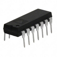
OP497GPZ Analog Devices Inc, OP497GPZ Datasheet - Page 11

OP497GPZ
Manufacturer Part Number
OP497GPZ
Description
IC OPAMP GP 500KHZ QUAD 14DIP
Manufacturer
Analog Devices Inc
Datasheet
1.OP497GPZ.pdf
(16 pages)
Specifications of OP497GPZ
Slew Rate
0.15 V/µs
Amplifier Type
General Purpose
Number Of Circuits
4
Gain Bandwidth Product
500kHz
Current - Input Bias
60pA
Voltage - Input Offset
80µV
Current - Supply
525µA
Current - Output / Channel
25mA
Voltage - Supply, Single/dual (±)
±2 V ~ 20 V
Operating Temperature
-40°C ~ 85°C
Mounting Type
Through Hole
Package / Case
14-DIP (0.300", 7.62mm)
Op Amp Type
Precision
No. Of Amplifiers
4
Bandwidth
500kHz
Supply Voltage Range
± 2V To ± 20V
Amplifier Case Style
DIP
No. Of Pins
14
Lead Free Status / RoHS Status
Lead free / RoHS Compliant
Output Type
-
-3db Bandwidth
-
Lead Free Status / RoHS Status
Lead free / RoHS Compliant, Lead free / RoHS Compliant
Available stocks
Company
Part Number
Manufacturer
Quantity
Price
GUARDING AND SHIELDING
To maintain the extremely high input impedances of the OP497,
care must be taken in circuit board layout and manufacturing.
Board surfaces must be kept scrupulously clean and free of
moisture. Conformal coating is recommended to provide a
humidity barrier. Even a clean PCB can have 100 pA of leakage
currents between adjacent traces; therefore, use guard rings
around the inputs. Guard traces are operated at a voltage close
to that on the inputs, as shown in Figure 34, so that leakage
currents become minimal. In noninverting applications, connect
the guard ring to the common-mode voltage at the inverting
input. In inverting applications, both inputs remain at ground;
therefore, the guard trace should be grounded. Place guard
traces on both sides of the circuit board.
UNITY-GAIN FOLLOWER
INVERTING AMPLIFIER
OP497
–
+
Figure 34. Guard Ring Layout and Connections
1/4
OP497
–
+
1/4
NONINVERTING AMPLIFIER
B
8
BOTTOM VIEW
–
OP497
+
1/4
PDIP
1
A
Rev. E | Page 11 of 16
OPEN-LOOP GAIN LINEARITY
The OP497 has both an extremely high gain of 2000 V/mV
typical and constant gain linearity. This enhances the precision
of the OP497 and provides for very high accuracy in high
closed-loop gain applications. Figure 35 illustrates the typical
open-loop gain linearity of the OP497.
–15
R
V
V
L
S
CM
= 10kΩ
= ±15V
= 0V
–10
Figure 35. Open-Loop Gain Linearity
–5
OUTPUT VOLTAGE (V)
T
T
A
A
= 125°C
= 25°C
0
5
10
OP497
15


