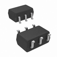
LMH6601QMGX/NOPB National Semiconductor, LMH6601QMGX/NOPB Datasheet - Page 23

LMH6601QMGX/NOPB
Manufacturer Part Number
LMH6601QMGX/NOPB
Description
IC AMP VFA 2.4V SHUTDOWN SC70-6
Manufacturer
National Semiconductor
Datasheet
1.LMH6601MGNOPB.pdf
(28 pages)
Specifications of LMH6601QMGX/NOPB
Amplifier Type
Voltage Feedback
Number Of Circuits
1
Output Type
Rail-to-Rail
Slew Rate
275 V/µs
Gain Bandwidth Product
155MHz
-3db Bandwidth
250MHz
Current - Input Bias
5pA
Voltage - Input Offset
1000µV
Current - Supply
9.6mA
Current - Output / Channel
180mA
Voltage - Supply, Single/dual (±)
2.4 V ~ 5.5 V, ±1.2 V ~ 2.75 V
Operating Temperature
-40°C ~ 85°C
Mounting Type
Surface Mount
Package / Case
SC-70-6, SC-88, SOT-363
Number Of Channels
1
Voltage Gain Db
66 dB
Common Mode Rejection Ratio (min)
56 dB
Input Offset Voltage
2.4 mV at 5 V
Operating Supply Voltage
3 V, 5 V
Supply Current
11.5 mA at 5 V
Maximum Operating Temperature
+ 85 C
Minimum Operating Temperature
- 40 C
Lead Free Status / RoHS Status
Lead free / RoHS Compliant
Other names
LMH6601QMGX
For any video line rate (HxV corresponding to the number of
Active horizontal and vertical lines), the speed requirements
can be estimated if the Horizontal Active (KH%) and Vertical
Active (KV%) numbers are known. These percentages cor-
respond to the percentages of the active number of lines
(horizontal or vertical) to the total number of lines as set by
VESA standards. Here are the general expressions and the
specific calculations for the SVGA line rate shown in
2.
Requiring that an “On” pixel is illuminated to at least 90% of
its final value before changing state will result in the rise/fall
time equal to, at most, the pixel time as shown below:
Assuming a single pole frequency response roll-off charac-
teristic for the closed loop amplifier used, we have:
Rise/Fall times are 10%-90% transition times, which for a 2
V
1.6V (80% of 2V). So, the Slew Rate requirement can be cal-
culated as follows:
The LMH6601 specifications show that it would be a suitable
choice for video amplifiers up to and including the SVGA line
rate as demonstrated above.
For more information about this topic and others relating to
video amplifiers, please see Application Note 1013:
http://www.national.com/an/AN/AN-1013.pdf#page=1
CURRENT TO VOLTAGE CONVERSION
(TRANSIMPEDANCE AMPLIFIER (TIA))
Being capable of high speed and having ultra low input bias
current makes the LMH6601 a natural choice for Current to
Voltage applications such as photodiode I-V conversion. In
these type of applications, as shown in
photodiode is tied to the inverting input of the amplifier with
R
PP
F
set to the proper gain (gain is measured in Ohms).
video step would correspond to a total voltage shift of
Figure 12
below, the
Table
(5)
(6)
(7)
(8)
23
FIGURE 12. Typical Connection of a Photodiode Detector
With the LMH6601 input bias current in the femto-amperes
range, even large values of gain (R
put error term appreciably. This allows circuit operation to a
lower light intensity level which is always of special impor-
tance in these applications. Most photo-diodes have a rela-
tively large capacitance (C
a photo-diode designed for higher sensitivity to light because
of its larger area. Some applications may run the photodiode
with a reverse bias in order to reduce its capacitance with the
disadvantage of increased contributions from both dark cur-
rent and noise current.
capacitance plot vs. reverse bias for reference.
FIGURE 13. Typical Capacitance vs. Reverse Bias
(Source: OSI Optoelectronics)
to an op amp
Figure 13
D
) which would be even larger for
shows a typical photodiode
F
) do not increase the out-
www.national.com
20136459
20136458


