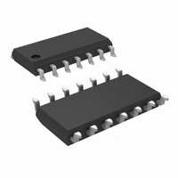
LPC660IMX/NOPB National Semiconductor, LPC660IMX/NOPB Datasheet - Page 12

LPC660IMX/NOPB
Manufacturer Part Number
LPC660IMX/NOPB
Description
IC OP AMP QUAD LOPWR CMOS 14SOIC
Manufacturer
National Semiconductor
Datasheet
1.LPC660AIMNOPB.pdf
(17 pages)
Specifications of LPC660IMX/NOPB
Amplifier Type
General Purpose
Number Of Circuits
4
Output Type
Rail-to-Rail
Slew Rate
0.11 V/µs
Gain Bandwidth Product
350kHz
Current - Input Bias
0.002pA
Voltage - Input Offset
1000µV
Current - Supply
160µA
Current - Output / Channel
40mA
Voltage - Supply, Single/dual (±)
4.75 V ~ 15.5 V, ±2.38 V ~ 7.75 V
Operating Temperature
-40°C ~ 85°C
Mounting Type
Surface Mount
Package / Case
14-SOIC (3.9mm Width), 14-SOL
Number Of Channels
4
Voltage Gain Db
120 dB
Common Mode Rejection Ratio (min)
63 dB
Input Offset Voltage
6 mV at 5 V
Operating Supply Voltage
9 V, 12 V
Supply Current
0.24 mA at 5 V
Maximum Operating Temperature
+ 85 C
Maximum Dual Supply Voltage
+/- 7.5 V
Minimum Operating Temperature
- 40 C
Lead Free Status / RoHS Status
Lead free / RoHS Compliant
-3db Bandwidth
-
Lead Free Status / Rohs Status
Details
Other names
*LPC660IMX
*LPC660IMX/NOPB
LPC660IMX
*LPC660IMX/NOPB
LPC660IMX
www.national.com
Application Hints
(Input pins are lifted out of PC board and soldered directly to components.
All other pins connected to PC board.)
BIAS CURRENT TESTING
The test method of Figure 7 is appropriate for bench-testing
bias current with reasonable accuracy. To understand its
operation, first close switch S2 momentarily. When S2 is
opened, then
A suitable capacitor for C2 would be a 5 pF or 10 pF silver
mica, NPO ceramic, or air-dielectric. When determining the
magnitude of I
FIGURE 7. Simple Input Bias Current Test Circuit
−
, the leakage of the capacitor and socket
FIGURE 6. Air Wiring
(Continued)
01054725
01054724
12
must be taken into account. Switch S2 should be left shorted
most of the time, or else the dielectric absorption of the
capacitor C2 could cause errors.
Similarly, if S1 is shorted momentarily (while leaving S2
shorted)
where C
Typical Single-Supply Applications
Note: A 5V bias on the photodiode can cut its capacitance by a factor of 2
or 3, leading to improved response and lower noise. However, this bias on
the photodiode will cause photodiode leakage (also known as its dark
current).
Note: (Upper limit of output range dictated by input common-mode range;
lower limit dictated by minimum current requirement of LM385.)
(V
+
= 5.0 V
Photodiode Current-to-Voltage Converter
x
is the stray capacitance at the + input.
DC
Micropower Current Source
)
01054718
01054717


