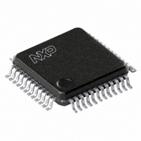
SC16C752BIB48,151 NXP Semiconductors, SC16C752BIB48,151 Datasheet - Page 28

SC16C752BIB48,151
Manufacturer Part Number
SC16C752BIB48,151
Description
IC DUAL UART 64BYTE 48LQFP
Manufacturer
NXP Semiconductors
Datasheet
1.SC16C752BIBS128.pdf
(47 pages)
Specifications of SC16C752BIB48,151
Number Of Channels
2, DUART
Package / Case
48-LFQFP
Fifo's
64 Byte
Voltage - Supply
2.5V, 3.3V, 5V
With Auto Flow Control
Yes
With False Start Bit Detection
Yes
With Modem Control
Yes
Mounting Type
Surface Mount
Voltage
2.25 V ~ 5.5 V
Data Rate
5 Mbps
Supply Voltage (max)
5.5 V
Supply Voltage (min)
2.25 V
Supply Current
4.5 mA
Maximum Operating Temperature
+ 85 C
Minimum Operating Temperature
- 40 C
Mounting Style
SMD/SMT
Operating Supply Voltage
2.5 V or 3.3 V or 5 V
Lead Free Status / RoHS Status
Lead free / RoHS Compliant
Features
-
Lead Free Status / Rohs Status
Lead free / RoHS Compliant
Other names
935274411151
SC16C752BIB48-S
SC16C752BIB48-S
SC16C752BIB48-S
SC16C752BIB48-S
Available stocks
Company
Part Number
Manufacturer
Quantity
Price
Company:
Part Number:
SC16C752BIB48,151
Manufacturer:
NXP Semiconductors
Quantity:
10 000
NXP Semiconductors
SC16C752B
Product data sheet
7.10 Enhanced Feature Register (EFR)
7.9 Interrupt Identification Register (IIR)
The IIR is a read-only 8-bit register which provides the source of the interrupt in a
prioritized manner.
Table 17.
The interrupt priority list is shown in
Table 18.
This 8-bit register enables or disables the enhanced features of the UART.
shows the Enhanced Feature Register bit settings.
Table 19.
Bit
7:6
5
4
3:1
0
Priority
level
1
2
2
3
4
5
6
Bit
7
6
Symbol
EFR[7]
EFR[6]
Symbol
IIR[7:6]
IIR[5]
IIR[4]
IIR[3:1]
IIR[0]
IIR[5]
0
0
0
0
0
0
1
Interrupt Identification Register bits description
Interrupt priority list
Enhanced Feature Register bits description
Description
CTS flow control enable.
RTS flow control enable.
All information provided in this document is subject to legal disclaimers.
Description
Mirror the contents of FCR[0]
RTSn/CTSn LOW-to-HIGH change of state
1 = Xoff/Special character has been detected
3-bit encoded interrupt. See
Interrupt status.
logic 0 = CTS flow control is disabled (normal default condition)
logic 1 = CTS flow control is enabled. Transmission will stop when a HIGH
signal is detected on the CTSn pin.
logic 0 = RTS flow control is disabled (normal default condition)
logic 1 = RTS flow control is enabled. The RTSn pin goes HIGH when the
receiver FIFO halt trigger level TCR[3:0] is reached, and goes LOW when the
receiver FIFO resume transmission trigger level TCR[7:4] is reached.
IIR[4]
0
0
0
0
0
1
0
5 V, 2.2 V and 2.5 V dual UART, 5 Mbit/s (max.), with 64-byte FIFOs
logic 0 = an interrupt is pending
logic 1 = no interrupt is pending
Table 17
Rev. 6 — 30 November 2010
IIR[3]
0
1
0
0
0
0
0
shows Interrupt Identification Register bit settings.
IIR[2]
1
1
1
0
0
0
0
Table
IIR[1]
1
0
0
1
0
0
0
18.
Table
18.
IIR[0]
0
0
0
0
0
0
0
Source of the interrupt
Receiver Line Status error
Receiver time-out interrupt
RHR interrupt
THR interrupt
Modem interrupt
Received Xoff signal/ special
character
CTSn, RTSn change of state from
active (LOW) to inactive (HIGH)
SC16C752B
© NXP B.V. 2010. All rights reserved.
Table 19
28 of 47


