EVAL-ADF7020DB1 Analog Devices Inc, EVAL-ADF7020DB1 Datasheet
EVAL-ADF7020DB1
Specifications of EVAL-ADF7020DB1


Related parts for EVAL-ADF7020DB1


EVAL-ADF7020DB1 Summary of contents
Page 1
... PC Software for Register Programming Loop filter setup for operation at 38.4kbps Table 1: Ordering Codes Board Number RF Band 3 EVAL-ADF70XXMB 4 EVAL-ADF70XXMB2 EVAL-ADF7020DB1 902 MHz – 928 MHz EVAL-ADF7020DB2 862 MHz - 870 MHz EVAL-ADF7020DB3 433 MHz - 445 MHz EVAL-ADF7020-1DB4 405 MHz - 435 MHz EVAL-ADF7020-1DB6 470 MHz - 510 MHz EVAL-ADF7020-1DB7 310 MHz – ...
Page 2
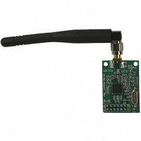
... EVAL-ADF7020-XDBX HARDWARE DESCRIPTION The RF module, which is plugged into the mother board, consists of the ADF7020 or ADF7020-1 device, output matching circuit optimized for operation in a certain frequency band, harmonic filter, PLL loop filter, de-coupling and xtal. This RF module provides a low-cost, optimally matched RF reference design which you can use as a starting point for your design ...
Page 3
... EVAL-ADF7020- 1DBX boards is shown in Figure7. If you are using a different length of PCB track to the ADI Evaluation boards you need to take this into consideration. ADIsimPLL will give you the total external inductance (chip inductor + PCB track) needed for a given frequency range so that your desired frequency band lies in the middle of the range where possible ...
Page 4
... EVAL-ADF7020-XDBX Figure 8. EVAL-ADF70XXMB Mother Board Circuit Diagram Preliminary Technical Data Rev Page ...
Page 5
... Preliminary Technical Data Figure 9. RF Module (LC harmonic filter) Circuit Diagram used for ADF7020DB3 and for all ADF7020-1 daughter boards (DB4, DB5, DB6, DB7 and DB8) Rev Page EVAL-ADF7020DBX ...
Page 6
... EVAL-ADF7020-XDBX Figure 10. RF Module (Dielectric Filter version) Circuit Diagram used for ADF7020DB1 and ADF7020DB2 Preliminary Technical Data Rev Page ...
Page 7
... For direct programming of the ADF7020/ADF7020-1 , click on the Registers button. This allows you to enter Hex values into individual registers. This is useful for de-bugging the register settings that you will use in your embedded microcontroller Figure 11. Software Front Panel Display Rev Page EVAL-ADF7020DBX ...
Page 8
... ADF7020/ADF7020-1. Initial Setup As described in the Hardware Description section, the evaluation board is divided into two module containing the ADF7020 and a mother-board which accepts the RF module and contains the power supply block and some I/O pins. You need to mount the RF module onto the mother- board, ensuring correct alignment by having the drill-holes in the module above the screw-holders on the mother board ...
Page 9
... Test Procedure for the ADF7020/ADF7020 mode Figure 13. Evaluation board setup for Rx mode Use a supply of 3V and the setup as shown in Figure 13 important to note that the ADF7020/ADF7020-1 uses a low-IF architecture where the IF is operating at 200kHz. This means the LO frequency should be set to 200kHz below the incoming RF frequency ...
Page 10
... EVAL-ADF7020-XDBX 13. If you don’t have a built-in BER tester you can estimate the sensitivity point, by reducing the level on the frequency generator until you see the RxTxData waveform ‘flickering’ which corresponds to errors in the recevied data. Typically if you see a flicker/error once per second you can roughly estimate this to be the sensitivity point ...
Page 11
... OR ADF7020-1DBX The EVAL-ADF70XXMB2 boards which contain an embedded microcontroller running a wireless network protocol is the simplest way to setup and RF Link. If you are using the EVAL- ADF70XXMB boards it is still possible to setup a basic link using the antennas and software provided. The most straight- forward way to do this is to have one board acting as a dedicated Transmitter and one board as the dedicated Receiver ...
Page 12
... SNR and modulation quality of the FSK signal recommended to use a LBW > 1.5 x Datarate. So for the defulat filter on the Eval Board, this gives a max. datarate close to 38.4kbps. If you want to operate the board at higher data-rates you need to modify the loop filter according ...
Page 13
... Preliminary Technical Data BILL OF MATERIALS Table 4. Bill Of Materials for the EVAL-ADF7020DBX and EVAL-ADF7020-1DBX Daughter Boards (Common to all versions) Qty Name C5,C7,C11,C14,C20, 8 C22,C25,C28 2 C8,C30 C15 C4,C6,C10,C12,C19, 8 C21,C26,C27 2 C23,C24 5 C13,C29,C31,C32,C33 R1 Value Tolerance PCB Decal 0.1uF ±10% 0402 10uF ±10% 0805 10nF ±10% 0402 22nF ± ...
Page 14
... EVAL-ADF7020-XDBX Table 5. Bill Of Materials for components specific to EVAL-ADF7020DB1 Daughter Board Qty Name Value 1 C1 2.7pF 1 C2 8.2pF 1 C3 3.0pF 1 L1 4.3nH 1 L2 8.7nH L3 Not inserted 1 R4 910r 1 R5 180r 1 C16 270pF 1 C17 33nF 1 C18 1.5nF 1 Y1 11.0592MHz 1 Y2 Table 6. Bill Of Materials for components specific to EVAL-ADF7020DB2 Daughter Board ...
Page 15
... Preliminary Technical Data Table 7. Bill Of Materials for components specific to EVAL-ADF7020DB3 Daughter Board Qty Name Value 1 C1 4.7pF 1 C2 10pF 1 C3 6.8pF 1 L1 13nH 1 L2 27nH L3 Not Inserted 1 L4 22nH 1 L5 20nH 1 R4 910r 1 R5 180r 2 C34,C36 Not Inserted 1 C35 6.8pF ...
Page 16
... EVAL-ADF7020-XDBX Table 8. Bill Of Materials for components specific to EVAL-ADF7020-1DB4 Daughter Board. Qty Name Value Matching 1 C1 4.7pF 1 C2 8.2pF 1 C3 4.7pF 1 L1 18nH 1 L2 36nH VCO Tank Inductor 1 L3 6.2nH Harmonic Filter 1 L4 27nH 1 L5 30nH 1 C35 5.6pF 2 C34,C36 Not Inserted Loop Filter ...
Page 17
... Preliminary Technical Data Table 9. Bill Of Materials for components specific to EVAL-ADF7020-1DB6 Daughter Board. Qty Name Value Matching 1 C1 3.9pF 1 C2 8.2pF 1 C3 3.9pF 1 L1 13nH 1 L2 30nH VCO Tank Inductor 1 L3 2.7nH Harmonic Filter 1 L4 18nH 1 L5 20nH 1 C35 5.6pF 2 C34,C36 Not Inserted ...
Page 18
... EVAL-ADF7020-XDBX Table 10. Bill Of Materials for components specific to EVAL-ADF7020-1DB7 Daughter Board. Qty Name Value Matching 1 C1 5.6pF 1 C2 10pF 1 C3 6.8pF 1 L1 30nH 1 L2 56nH VCO Tank Inductor 1 L3 13nH Harmonic Filter 1 L4 51nH 1 L5 47nH 1 C35 6.8pF 2 C34,C36 Not Inserted Loop Filter ...
Page 19
... Preliminary Technical Data Table 11. Bill Of Materials for components specific to EVAL-ADF7020-1DB8 Daughter Board. Qty Name Value Matching 1 C1 12pF 1 C2 18pF 1 C3 10pF 1 L1 100nH 1 L2 200nH VCO Tank Inductor 1 L3 22nH Harmonic Filter 1 L4 150nH 1 L5 130nH 1 C35 15pF 2 C34,C36 Not Inserted ...