EVAL-ADF7020DB1 Analog Devices Inc, EVAL-ADF7020DB1 Datasheet - Page 2
EVAL-ADF7020DB1
Manufacturer Part Number
EVAL-ADF7020DB1
Description
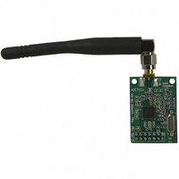
BOARD EVAL ADF7020 902-928MHZ
Manufacturer
Analog Devices Inc
Datasheet
1.EVAL-ADF7020DB2.pdf
(19 pages)
Specifications of EVAL-ADF7020DB1
Module/board Type
Evaluation Board
For Use With/related Products
ADF7020 928MHz
Lead Free Status / RoHS Status
Contains lead / RoHS non-compliant


EVAL-ADF7020-XDBX
HARDWARE DESCRIPTION
The RF module, which is plugged into the mother board,
consists of the ADF7020 or ADF7020-1 device, output
matching circuit optimized for operation in a certain frequency
band, harmonic filter, PLL loop filter, de-coupling and xtal.
This RF module provides a low-cost, optimally matched RF
reference design which you can use as a starting point for your
design. A low-cost BOM is achieved by using a 2-layer PCB, a
low-cost xtal, and a simple combined output matching circuit
which eliminates the need for an external switch.
There are two different versions of the daughter card, one
which uses a low-cost dielectric harmonic filter from Murata
the other which uses a standard LC harmonic filter. Gerber files
for both are available for download on the ADF7020 product
page. Schematics are shown in Figures 9 and 10. The DB1 and
DB2 boards use the dielectric filter while all other boards use
the LC filter.
The silk screen for the basic mother board is shown in Figure 4.
Figure 2. Dielectric Filter version – silkscreen
Figure 1: .LC Filter version-silkscreen
Rev. Pr C | Page 2 of 19
The mother board (MB) comes with a cable for connecting to
the printer port of a PC. The cable diagram is shown in Figure
5. The MB can be supplied directly with an external supply of
2.3V to 3.6V or a battery voltage from 3V to 9V by switching in
a regulator using jumper K3. There is an on-board
11.0592MHz AT crystal. The crystal combined with 33pF shunt
capacitors provide the low cost frequency reference for the local
oscillator.
The necessary SMA connectors are included to interface the
part to the measurement instrument (Normally a spectrum
analyzer in Tx mode and a RF signal generator in Rx mode).
Care should be taken to ensure that no DC level exists at the
ANTENNA SMA.
The parallel port has 5V voltage levels, so there is a voltage
divider to bring this down to levels acceptable to the ADF7020
/ADF7020-1 device.
Figure 3. . Mother Board Silkscreen – component side view
Figure 4. PC Cable Diagram
Preliminary Technical Data
Related parts for EVAL-ADF7020DB1
Image
Part Number
Description
Manufacturer
Datasheet
Request
R


Part Number:
Description:
BOARD EVAL FOR SI270X-A
Manufacturer:
Silicon Laboratories Inc
Datasheet:

Part Number:
Description:
BUCK CONV REF DESIGN KIT IP1201
Manufacturer:
International Rectifier
Datasheet:
Part Number:
Description:
BOARD DEMO SYNC DUAL BUCK CNVTER
Manufacturer:
International Rectifier
Datasheet:
Part Number:
Description:
BOARD DEMO SYNC BUCK CONVETER
Manufacturer:
International Rectifier
Datasheet:

Part Number:
Description:
EVALBOARD/EB Omnidirectional microphone - Analog
Manufacturer:
Analog Devices
Datasheet:
Part Number:
Description:
EVALBOARD/EB Omnidirectional microphone - Analog
Manufacturer:
Analog Devices
Datasheet:


Part Number:
Description:
BOARD EVAL LED DRIVER LT3756
Manufacturer:
Linear Technology
Datasheet:

Part Number:
Description:
BOARD EVAL FOR AD7741/7742
Manufacturer:
Analog Devices Inc
Datasheet:

Part Number:
Description:
±1.7g Dual-Axis IMEMS Accelerometer Evaluation Board
Manufacturer:
Analog Devices Inc
Datasheet:

Part Number:
Description:
IC MULTIPLIER ANALOG 8-SOIC T/R
Manufacturer:
Analog Devices Inc
Datasheet:

Part Number:
Description:
IC ANALOG MULTIPLIER 8-DIP
Manufacturer:
Analog Devices Inc
Datasheet:
Part Number:
Description:
IC ANALOG MULTIPLIER 8-SOIC
Manufacturer:
Analog Devices Inc
Datasheet:
Part Number:
Description:
IC ANALOG MULTIPLIER 8-DIP
Manufacturer:
Analog Devices Inc
Datasheet: